Do you have a question about the Qualitrol OTIWTI AKM345 GEN3 and is the answer not in the manual?
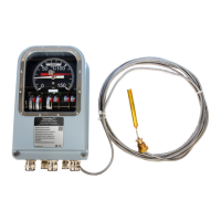
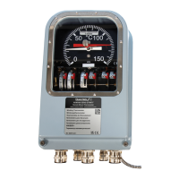
Overview of the temperature indicator for transformers.
Explains the bellows type technology and how the device indicates temperature.
Procedure for verifying factory calibration of the instrument.
Method for simulating winding temperature using thermal image.
Describes available outputs for SCADA or monitoring systems.
Details the RS-485 Modbus communication option.
Details storage and operating temperature, and enclosure protection.
Specifies dielectric isolation and switch ratings.
Covers dial accuracy, seismic, vibration, and shock stability.
Lists SCADA output signals, power supply, and EMC immunity.
General safety precautions for operating the device.
Instructions for routing the capillary tube to prevent damage.
Important warnings and requirements for switch wiring.
Safety warnings and guidelines for electrical connections.
Details mains ground wiring and required overcurrent protection.
Instructions for connecting and grounding the 4-20mA current loop.
Notes on scaling the 0-5 V DC output.
General guidance on mounting the AKM345 enclosure.
Details mounting styles and dimensions for the enclosure.
Provides dimensional drawings for standard and universal mounts.
Illustrates the seismic mounting style.
General instructions for probe installation.
Guidance on installing the probe in dry or oil-filled pockets.
Technical drawings of various probe types with dimensions.
How to open and prop open the front cover for access.
Step-by-step procedure for opening the front cover.
Step-by-step instructions for removing the front cover.
Information on specified cable gland types and quantities.
Explains how to wire the switches and terminal numbering.
Wiring example for internal matching resistance connections.
Information on power input requirements for certain configurations.
Wiring examples for powered and Pt100 remote outputs.
Wiring example for RS-485 Modbus communication.
Procedure for adjusting each switch's setpoint.
Procedure for adjusting the switching differential.
Procedure to adjust TD50/TD76 matching resistance using a graph.
Details the TD50(5AMP) option for winding simulation.
How to set two separate winding simulations with dual gradient.
Using 1A or 5A external units for matching resistance.
Default settings for MODBUS communication.
How the device records and reports events via MODBUS.
Overview of MODBUS register ranges and supported function codes.
Details MODBUS input registers for alarms, temperature, and firmware.
Describes MODBUS discrete input registers, specifically for alarm status.
Lists MODBUS holding registers for dial selection, slave ID, baud rate, and alarms.
Special notes regarding system time and temperature display.
Checks for steady input current and proper resistance setting.
Checks for proper supply voltage and wiring arrangements.
| Category | Measuring Instruments |
|---|---|
| Model | AKM345 GEN3 |
| Manufacturer | Qualitrol |
| Sensing Element | RTD (Resistance Temperature Detector) |
| Analog Output | 4-20 mA |
| Communication | Modbus RTU |
| Display | LCD |
| Accuracy | ±1°C |
| Type | Oil Temperature Indicator/Winding Temperature Indicator |
| Power Supply | 24 VDC |
| Temperature Range | -40 to 180°C |
| Wireless Communication | Optional |
| Enclosure Rating | IP66 |
| Mounting | Wall |
| Compatibility | Transformers |