Do you have a question about the Qualitrol 509-200 and is the answer not in the manual?
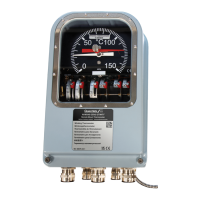
Overview of the QualiTROL Electronic Cooling Monitor (ETM) for liquid-filled transformers.
Details the controls, indicators, and modules of the QualiTROL ETM.
Provides step-by-step instructions for mounting, wiring, and powering the Transformer Monitor.
Explains automatic operation, parameter viewing, and system programming.
Presents a detailed functional specification of the unit.
Contains wiring diagrams and configuration tables for reference.
Describes the display, keypad, and status indicators on the front panel.
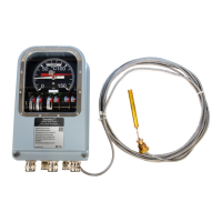
Describes the RTD input module for temperature measurement.
Explains the CT input module for current and temperature monitoring.
Details the AC voltage input module for monitoring AC voltages.
Describes the potentiometer input module for level and flow measurement.
Explains the DC voltage input module for transducer outputs.
Details the current input module for 0-1mA or 4-20mA signals.
Describes the dry contact closure module for switch monitoring.
Explains the powered contact closure module for powered switch monitoring.
Details the nine isolated output contacts for control and alarms.
Describes the four mA current outputs for remote indication/SCADA.
Explains digital communication capabilities via RS-485 and fiber optic.
Covers enclosure and panel mounting styles for the transformer monitor.
Details the power supply connections for different unit configurations.
Explains the wiring for the optional heater for enclosure/panel/rack mounts.
Provides wiring instructions for the RTD input module.
Details wiring for the CT input module for current and temperature.
Explains AC voltage input module wiring with a voltage sensor.
Provides wiring for the potentiometer input module for level/flow measurement.
Details wiring for the DC voltage input module with a voltage transducer.
Explains wiring for the current input module for mA signals.
Provides wiring for the dry contact closure input module.
Details wiring for the powered contact closure input module.
Describes the monitor's automatic monitoring and control upon power-up.
Explains how to view parameters in scrolling mode.
Details navigation and interaction within the monitor's menu system.
Describes how to view and reset maximum parameter readings.
Explains how to view and reset minimum parameter readings.
Details how to view and interact with set point values.
Explains how to view readings for the cooling monitor system.
Covers accessing and using the program mode for parameter changes.
Introduces the Cooling System Monitor setup and normal operations.
Details the menu structure and navigation for the cooling monitor.
Presents a functional wiring diagram for the transformer monitor.
| Brand | Qualitrol |
|---|---|
| Model | 509-200 |
| Category | Measuring Instruments |
| Language | English |