16 www.quantumrehab.com Quantum 610
III. YOUR POWER CHAIR
ELECTRICAL COMPONENTS
The electrical components are located inside the power base. The main circuit breaker is located on the front of the battery
tray. The controller connectors are located inside the power base. See figure 7.
Motor Connectors: This is where the controller connects to the motors.
Battery Connector: This is where the controller connects to the batteries.
Controller Connector: This is where the controller connects to the power base.
Main Circuit Breaker: The main circuit breaker is a safety feature built into your power chair. When the batteries and the
motors are heavily strained (e.g., from excessive loads), the main circuit breaker trips to prevent damage to the motors and
the electronics. If the circuit trips, allow your power chair to “rest” for approximately one minute. Next, push in the circuit
breaker button, turn on the controller, and continue normal operation. If the main circuit breaker continues to trip repeat-
edly, contact your Quantum Rehab Specialist.
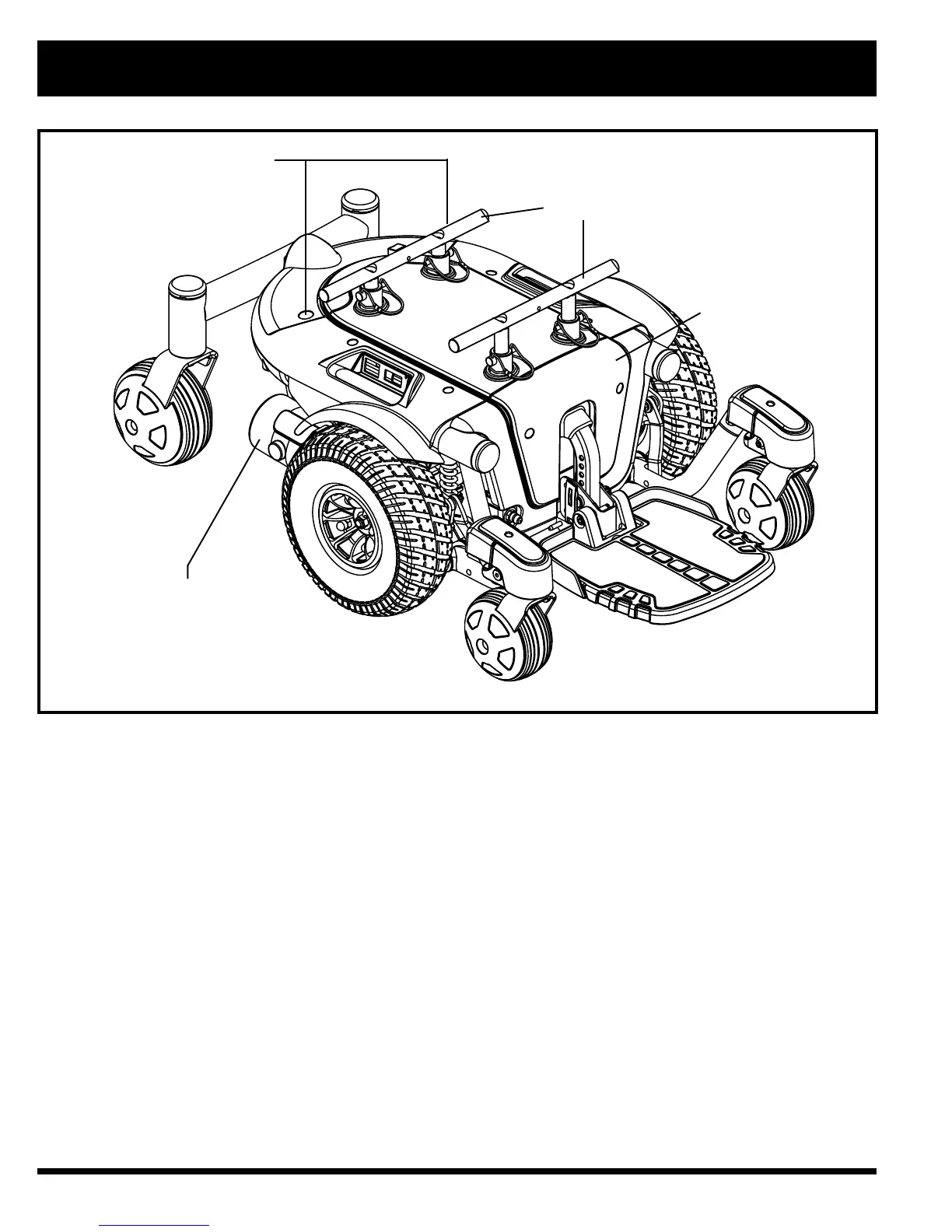
Figure 6. The Quantum 610 Power Base
MOTOR/BRAKE ASSEMBLY
REAR SHROUD FASTENERS
TRAPEZE BARS
FRONT COVER