7
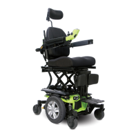
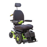
The J4E Power Chair
Your power chair has two main assemblies: the seat assembly
and the power base assembly. Typically, the seat assembly
includes the armrests, seatback, and seat base. The power
base assembly includes two motor/brake assemblies, two
drive wheels, four caster wheels, two batteries, and wiring
harnesses. See J4E (page 4) and gure 1.
The spring tension on your power chair was factory set
to meet the needs of the demographic majority of users.
Do not adjust the tension of any spring on your power
chair.
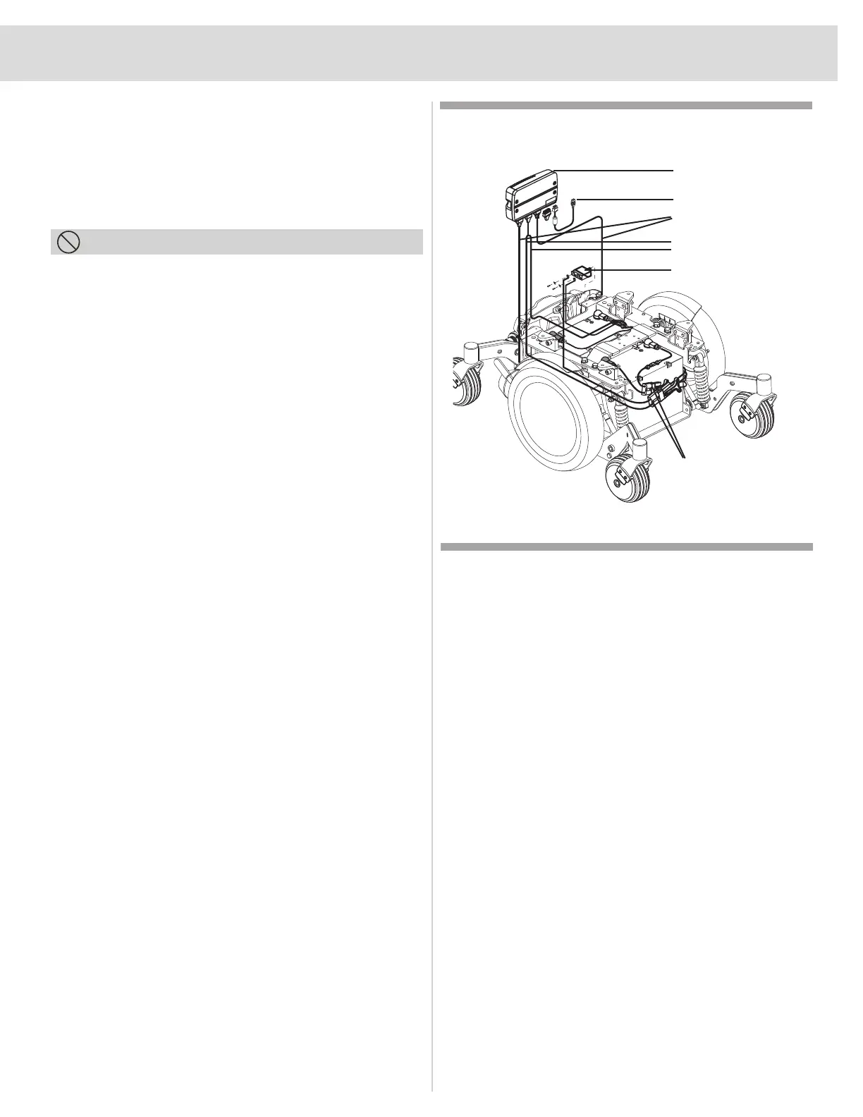
Electrical Components
The electrical components consist of the controller assembly,
the batteries, and the motors. The batteries, motors, and
controller power module (if equipped) are located on the
power base assembly. The controller is located on the seat
assembly. Connectivity between the controller and the
motors, batteries, and the battery charger is provided by one
or more wiring harnesses. See gure 1.
Controller Harness Connector: The controller harness
connector is where the controller plugs into the power base.
Each controller uses a dierent type of harness. Regardless of
which type of controller is used, the harness must be secured
to the seat assembly and not allowed to drag on the oor.
Motor Connectors: This is where the controller connects to
the motors.
Battery Connector: This is where the controller connects
to the batteries.
Controller Power Module: This enables the controller to
communicate with the batteries and the motors.
Main Circuit Breaker (located on the rear main frame): The
main circuit breaker is a safety feature built into your power
chair. When the batteries and the motors are heavily strained
(e.g., from excessive loads), the main circuit breaker trips to
prevent damage to the motors and the electronics. If the circuit
trips, allow your power chair to “rest” for approximately one
minute. Next, push in the circuit breaker button, then turn on
the controller, and continue normal operation. If the main circuit
breaker continues to trip repeatedly, contact your Quantum
Rehab Provider.
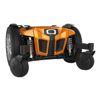
Figure 1. J4E Electrical Components
YOUR POWER CHAIR
PROHIBITED!
Controller Power Module
Controller Connector
To Battery Connectors
To Motor Connectors
Main Circuit Breaker
Quick Release
Battery Connectors