Scalar i6000 Installation Guide Super Doc 5
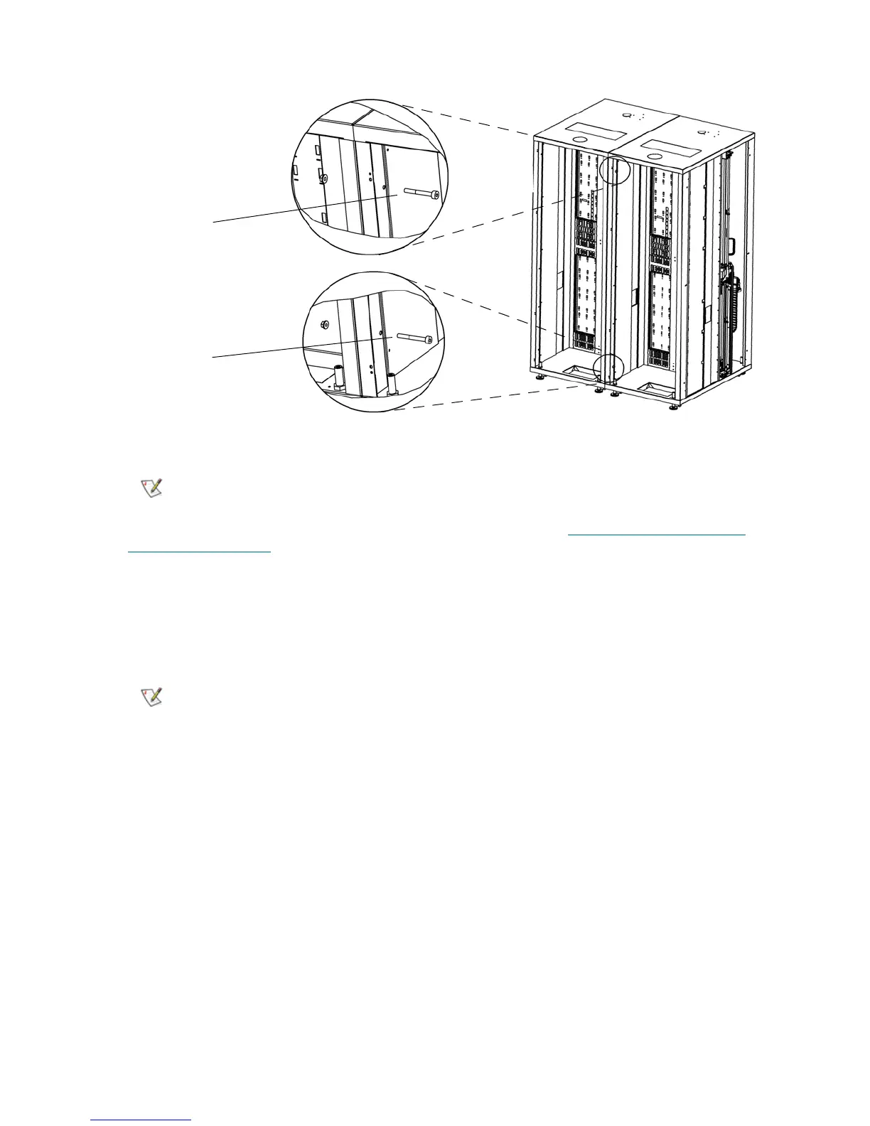
3 Tighten the bolts using the 6 mm hex wrench and the 13 mm open end wrench.
4 Once the frames are aligned and bolted properly together, proceed to Positioning the System Unit
(Same as Gen 1 Task) on page 5.
Positioning the System Unit (Same as Gen 1 Task)
For more information on location specifications, see the Scalar i6000 Planning Guide.
1 Verify the placement of the system unit.
2 Verify the following:
• There is an AC outlet within 10 feet (3.05 m) of the control module’s location.
• There is adequate clearance for the access and service doors.
• All raised floor tiles have been cut out accordingly to accommodate the power, SCSI, Fibre, and
Ethernet cables to any of the modules.
3 Position the system unit in its intended location.
4 Verify that the system unit is positioned correctly.
5 Ensure that the leveling legs are not resting on tiles that will need to be raised to accommodate cables
after the system unit has been installed.
Do not overtighten the bolts. Overtightening can damage the vertical frame
post structure.
The left parking module is at the left end of a dual-robotics multi-module
library.
back upper bolt
back lower bolt
 Loading...


