EN 15
Installation - Mechanical Components (AWD Conguration)
Installation - Electrical/Electronic Components
To install an All Wheel Drive conguration on your caravan, follow the same instructions outlined in the
previous ‘Installation - Mechanical Components’ sections. AWD set up follows the exact same process,
with the only difference being the orientation of the movers. In an AWD conguration, the movers
powering the rear axle of the vehicle must be orientated facing the front of the trailer (see Fig.12).
Ensure to follow the AWD conguration section of the Electrical/Electronic installation manual closely
to ensure that these motor assemblies work as intended and not against one another.
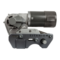
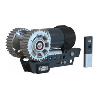
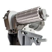
With the EM4446 Ego Enduro and EGO400 Titanium mover models, the process of engaging is a
manual one. To engage your motors, place the engagement tool (6) onto the motor spindle (Fig.2.G
or Fig.3.G) parallel to the ground at a position facing away from the wheel in question. To engage the
motor, rotate the engagement tool through 180deg rotating toward the wheel in question (see Fig.4 or
Fig.7). If you cross actuation bars have been mounted correctly, the process of engaging one mover,
should subsequently also engage the opposite side of the vehicle.
The engagement mechanism utilises a simple over-centre cam that pushes the rollers onto the tyres
and then locks into place automatically. If the mover has been installed correctly, at exactly 20mm
away from the tyres when disengaged, the amount of force provided onto the tyre by the roller will be
sufcient for most circumstances of use (Fig.6 or Fig.9).
Note: Irrespective of which side of the vehicle you are operating the engagement from, the tool should
always rotate toward the wheel to engage, and away from the wheel to disengage.
To disengage the rollers, simply ret the tool onto one of the spindles and rotate away from the tyre.
Please note that you will feel a small amount of resistance initially as you disengage the cam from its
locked position; the spring will then do the rest of the work and pull the roller away from the tyre and
into the fully disengaged position (Fig.5 or Fig.8).
Note that no tightening/torquing of the rear nuts/bolts (Fig.16.B and E) is required. These components
are in place purely to assist with the installation process and are not a method of afxation.
Please refer to manual supplied with electronics for wiring installation, operation instructions and
troubleshooting, or visit www.purpleline.co.uk/qtr-m003
Installation - Shark Clamp System (Fig.15) cont.
Mover Engagement/Disengagement
 Loading...