Rev 3.1 01/11/23 - 6 - Model 600 User Guide
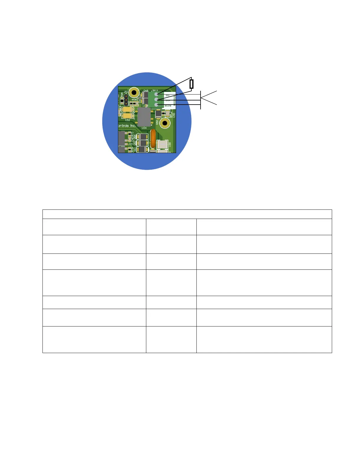
Figure 3 – End of Line Resistor
2.7 Wiring Types
The following chart contains the recommended wire types for the inputs and outputs.
Description
Usage
Cable, 2 Cond, 18 AWG, Unshld,
Strnd (RED, BLACK)
Belden 6300UE
Power Supply to Model 600 and digital input
monitor points
Cable, 2 Cond, 22 AWG, Shld, Solid
(RED, BLACK)
Belden 6520FE Temperature sensor and humidity inputs
Cable, 4 Cond, 20 AWG, Shld, Strnd 9
(RED, BLACK, WHITE, GREEN)
Belden 6402FE
Zone 1 combination temperature and humidity
sensor.
Cable, 4 Pair, 24 AWG, Unshld, Solid Belden 1245A2 Alarm outputs
Cable, 8 Cond, 18 AWG, Unshld, Sld,
T-Stat
Coleman 55308 HVAC control wiring
Cable, 2 Pair, 24 AWG, Shld, Strand
(WHT/BLU, BLU/WHT, WHT/ORG,
ORG/WHT)
Belden 88102 Modbus Cable
Table 1: Wire Matrix
2.8 Typical installation drawings
Below are some typical installation drawings for HVAC systems with Integrated Economizer control and when
the Model 600 is controlling the economizer damper directly. Please contact Quest Controls for assistance if
your application differs from these examples.