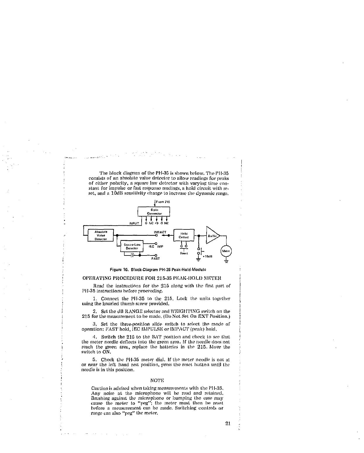
! The block diagram of tile PH-35 is shown below, The PII-35
! consists of Ill1 IlbSOItlte value detector to allow readings for pe_ll(s
of either polarity, a squnre law det0etor with varying time cnn-
i stant for impulse or fast response readings, a hold circuit with r_-
set, and a 1OdB sensitivity chnnge to increase the dyllamic range,
i Flam 215
6,pm
! CmlJ_ect°¢
INPU_
Del_¢tof J _ IEC _IMP
FAST
Figura 16. Brock-DiagramPH-35Poak,HotdModul_
OPI'_RATING PROCEDURE FOR 215-35 PEAK-IIOLI) MI'_'Z'F,R
Road the instructions for the 215 along with the first part t)f
PH-35 instructions heft)re proceeding.
1. Connect tile I'11-35 to tile 215. Lock the units togelher
using the knurled thunab screw provided,
2. Set tho dB l_,AN_E solector and "WF,IGIITING switeh on the
215 for tile meastlrement to be made. (Dt_ Not Sol, O11 EXT Position.)
3. Set the three-position slide switch to soh_ct tlw mode of
operation: FAST hold, IEC IlXlI_ULSI_ or IMPACT {peak) hold.
,I. Switch the 215 to tile BAT position and cheek to see thng
tile meter noodle deflects into tile green area. If tilt} needle does ]lot
reach the green area, replace tile batteries in tile 215. Mr)re tile
switch to ON,
5. Cheek the PII-35 meter diIIl. If tile meter needle is =lot al
or near tile left hand rest position, press the reset button until tht!
needle is in this position,
NOTE
Caution is advised when taking measttmments with tile PIII_]5.
Any noise ;it tile microphone will he reild and retained.
Brtl._llillg a_llinst the nlit2rophon[_ or htlnall[ng tile eas(! hilly
C_ltlse the motor to "po_"; the nl(!tor nlust then b(_ r_s_t
I)ofore it I'no_lstlrenlollt cllll I)e lllllCle, Swi/ehillg controls or
rtlllgO Call a]so "pt?g" tile nl_tel'.
21