_,_ _:,_ _,_.-r,,:'_¢ • , .. _ _ _ • _ _ ._,
Size: 3 x 3-1/2 9 2ol/8 inches with hack cover extcndhtg to
8-inch length.
Weight: 9 ounces.
Construction: Solid state integrated circuitry in rugged alumin-
um housing,
CONTROLS
FP_EQUENCY Band Selector -- A nine-position rotary switdl to
select the octave band filter desired from 31.5 Ilz to S Kllz. (31.5,
fi3, 125, 250, 500, 1K, 2K. ,IK. 8K Hertz).
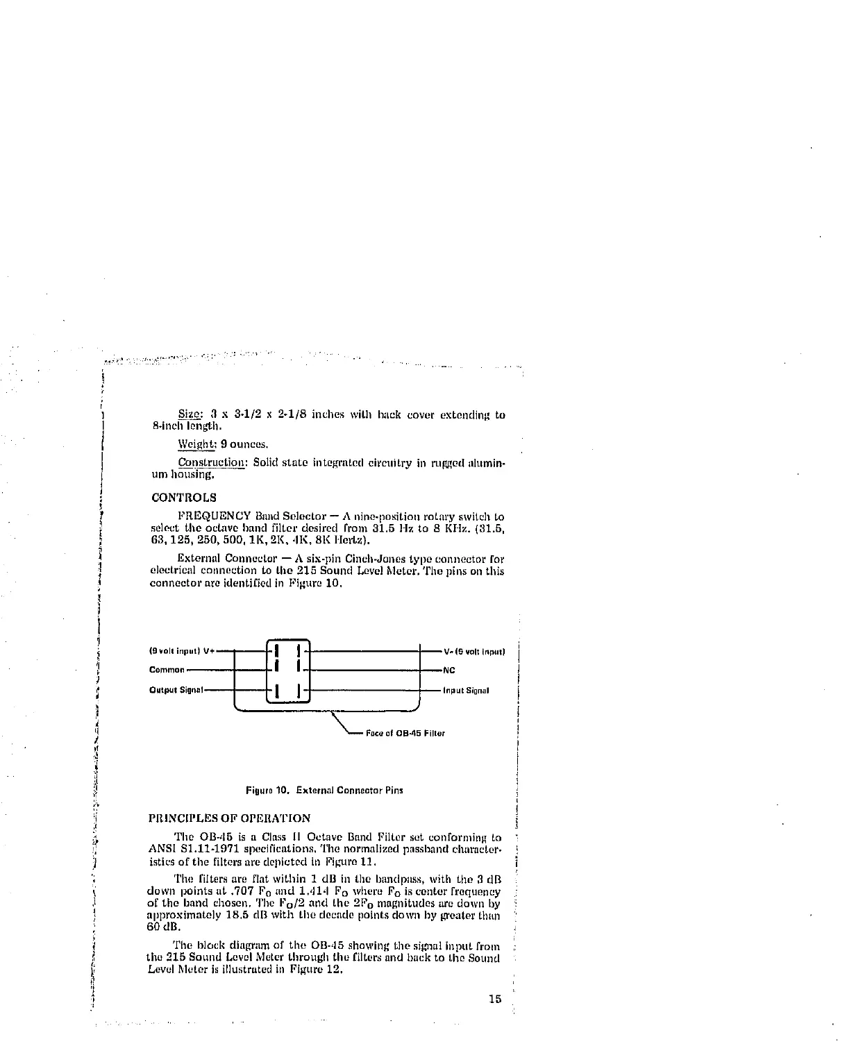
External Connector -- A six-pin Cinch-Jones type connector for
electrical connection to the 215 Sound Level Meter. The pins on this
connector are identified in Figure 10.
(O volt input) V+ --1"--_! ! I V- (9 volt input)
Commoll I_ NC
Output Signal-- Input Signal
_-.- Face of OB.45 Filter
Figut010. ExternalConnectorPins
PDdNC[PLES OF OPEItATION
The OB-d5 is a Class 11 Octave Band Filter set conforming to
ANSI $1.11-1971 specifications, The normalized passband character.
istics of the filters are depicted in Figure 11.
The filters are flat within 1 dB ill the Imndpass, with tile 3 dB
down points lit ,707 Fo lind 1,dl,I Fo where Fo is center freqtlency
of the band chosen. '1'11oFo/2 and the 2F o magnitudes are down by
npproximately 18.5 dB with the decade points down by greater than
60 dB.
The block diagram of the OB-,15 showing the signal input from
the 215 Sound Level Meter through tile filters and back to the Sound
Level Meter is illustrated in Figure 12,
15