Using lira liA.10OMV Mlliplor
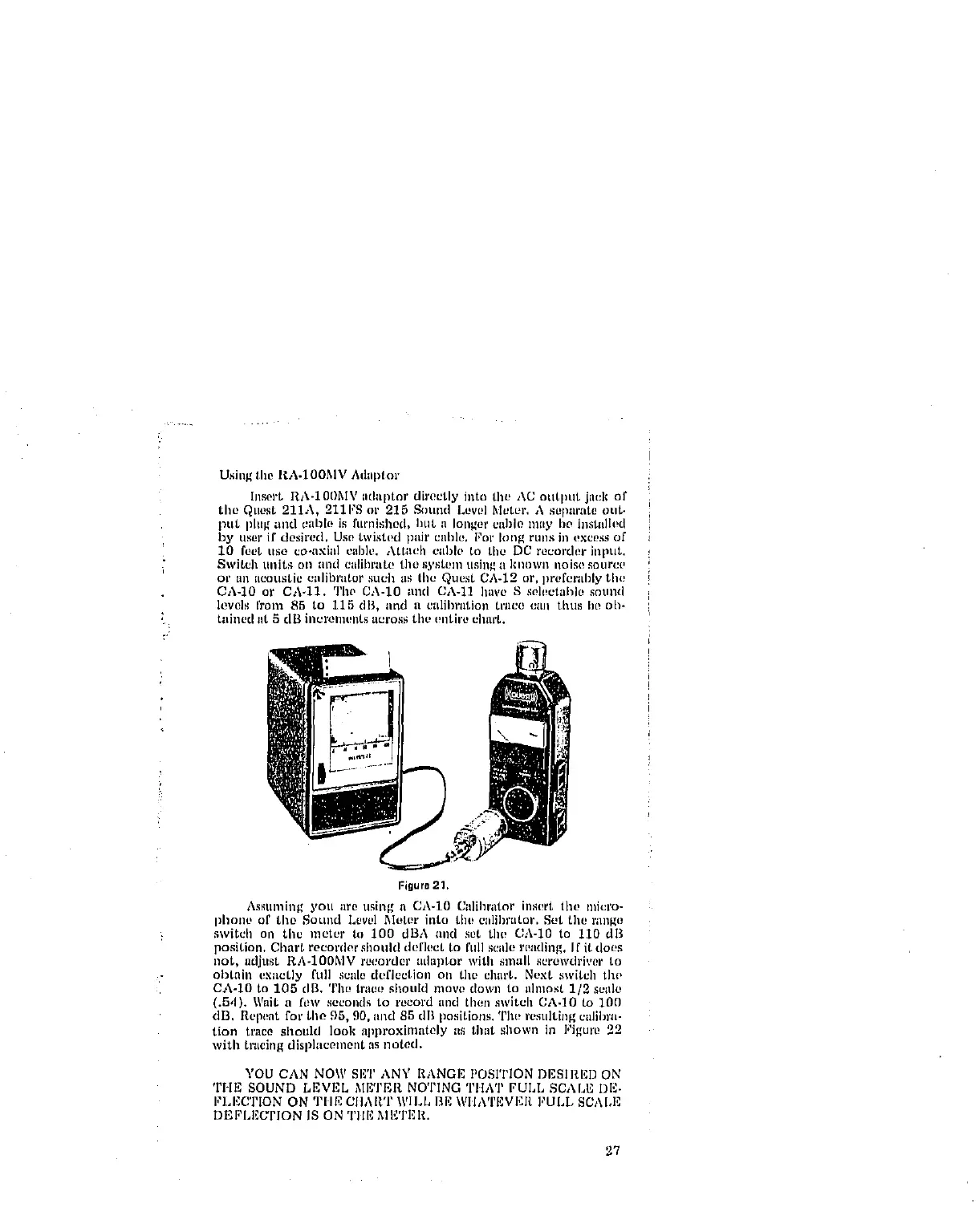
Insert RA-10I)MV iidlllitor directly iato tht, AC otltliut jau]¢ of
tile QLIOSt211A, 211FS or 215 Sound Levl!] Mt_tpr. h sepilrlit00tlt.
put plltg ;liKI clll3k! is ftlmishi)d> hilt a longer cable hilly lie iilstlllh!d
l_y user if dcsh'ed, Use twistl!d pair ciiH/,, for tong fUllS in t!xce_is of
10 feet liso co-axial cal)ie. Aitaell cilillo to the DC recorder illput.
Switch llllitS Oll lind eillihl_ltl! the s),st_ln tlsin_ i1klloWi1 iloJso iOllrCl,
or all acoustic ciilil)i'iitor such \is tile Quest CA-12 or, lirl!forlil)17 the
0A-10 or CA.11. Tlw CA-10 lind CA-11 have S selectallle sntlnd
levels from 85 to 115 dB, lind li etdil)riltioll tl'iico till\ thus lip oh-
tained lit 5 dil illt_ronlent_ ut2ros.,;tilt, (!nth'/b _lllu't+
Figure 21,
Assuming you are using a CA-10 Calihrator insert tilt, miei'o-
phone of the Sound Level Meter into tiu_ calibrator. Set the range
switcil oil the meter to 100 dBA and sot the CA-IO to 110 dB
position. Cllart recorder should deflect to full scale reading. If it does
not, adjust RA-100MV recorder aduptor with small screwdriver to
obtain exactly l'ull scale deflection on tim chart. Next switch tho
Ch-lO to 105 clB. Tile trace shoukl move down to almost 1/2 scale
(.5,1). Wait a ['oW seconds to record and then switch CA.IO to 100
dB. Repeat for tile 95, 90. iilld 85 dB positions. The resulting caliln'a-
tion trace should look approxiinately as that sllown ill Figure 22
with tracing displacement as noted.
YOU CAN NOW SET ANY RANGE POSITION DESIRED ON
THE SOUND LEVEL METER NOTING TIIAT FULL SCALE DE-
I,'LEC'rION ON TIlE CIIART WILL BE WIIA'rEvI':I_ FULL SCALE
DEI;'LEUI'ION IS ON Tlll'] MI_TER.
27