A.C. OUT Jack -- All output jack that furnishes nn AC voltage
of tile noise wave that has heen conditioned IW the weighting or
filter position selected and is proportional to the meter reading. The
jack acuepts a S,,vitehcraft, type 7S0-Thll-phlg or Oqtlivllle_It, This
Otl_J_tlt call be used for Illaglletic tapt_ or chart recorclJtlg j_tlrposes.
When recording ',vitil a DC chart recorder, the Quest Model
RA-100MV recorder adaptor is necess_lry to conw_rt tile AC si$1al to :
DO.
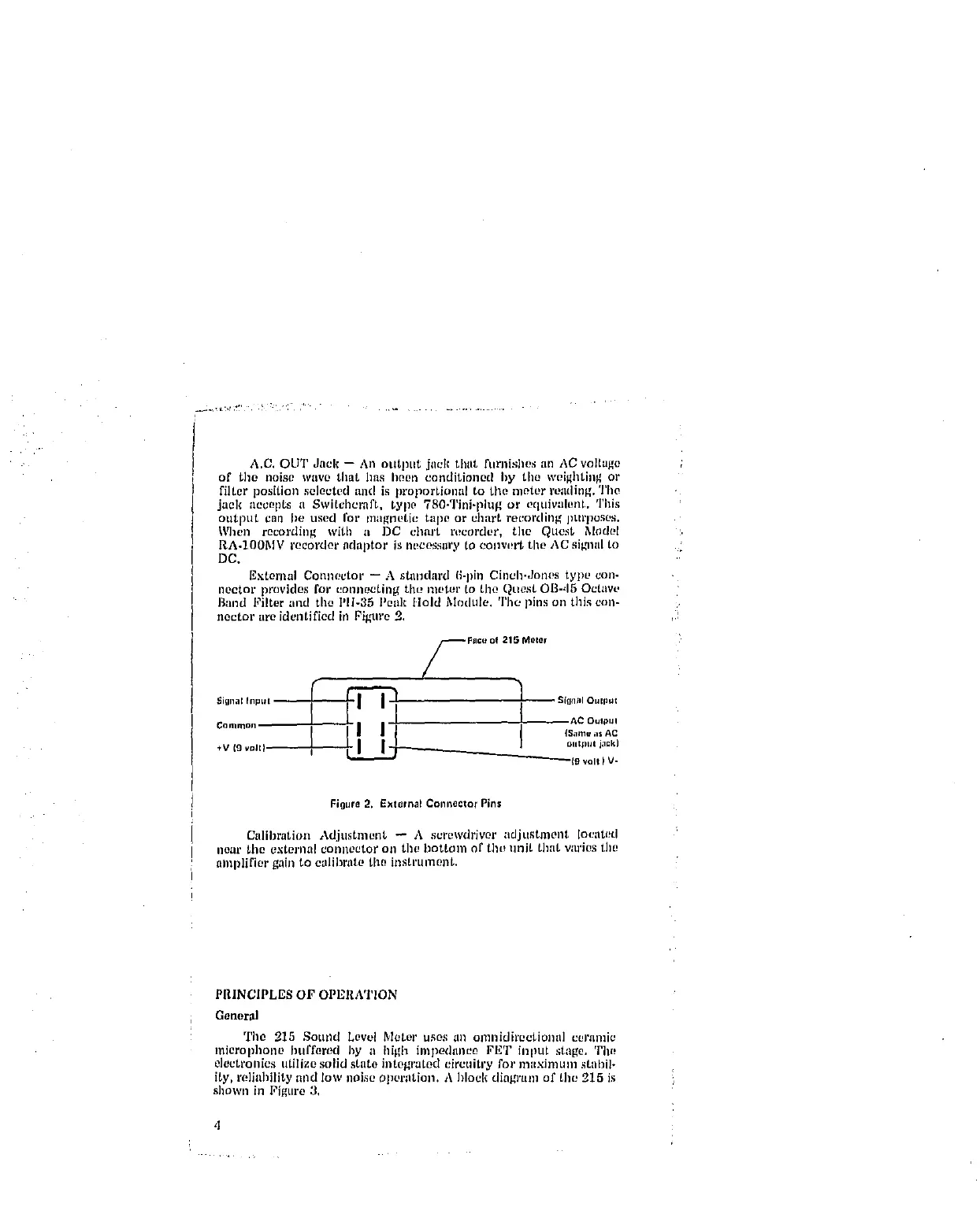
External Connector -- A standard fi-pin Cinch-Jones type con-
nector provkles for _onnecting tile hinter to tile Quest OB-_I5 Octave
Band Filter and tile Pli-35 Peak Hold Module. Thu pins ozl this eoll-
nector are idenUfied in Pigure 2,
Faco of 215 Meter
gigna* Input _ _ Silltl;tl Outp,t
ooo.... i illi I
N OIItllUt j,qCk)
_(O volt ) V-
Figure 2, Ex[ernat ColmectorPins
Calibration Adjustment -- A screwdriver adjustment located
*lear _he external connector on tile bottom of tht_ unit that wu'ies the
amplifier gain to calibrate tim instrument.
PRINCIPLES OF OPERATION
General
The 215 Sound Level Meter uses _lll omnidirectional ceramic
microphone buffered by a high impedance FET input stage. The
electl'onics utilize solid state integrated circuitry for maximunl stabil-
ity, reliability and low noise opcr;ition. A block diahmtm of tile 215 is
shown in Figure 3,
,t