6
PR-120 / PR-240
Installation:
CAUTION: Before you begin, make sure your mixer-amplier is disconnected from the power
source, with the power switch in the “OFF” position and all level controls turned completely down
(counterclockwise)
You may stack mixer-ampliers without using a cabinet or you may place a single mixer-amplier
on a surface with 12-inches (about 30cm) of air space around the unit for convection cooling.
When using an equipment rack, do not mount units directly on top of each other. Allow 2U be-
tween units for convection cooling. The side walls of the rack should be a minimum of 2-inches
(about 5cm) away from the amplier sides, and the back of the rack should be a minimum of
4-inches (about 10cm) from the mixer-amplier rear panel.
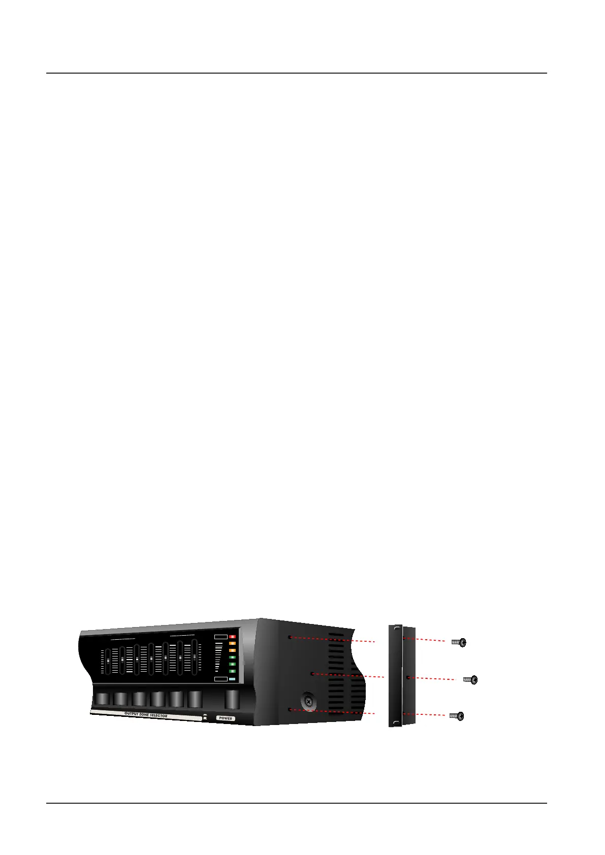
How to attach rack ears
1. Locate the two rack ears and six rack-ear screws supplied.
2. Place a rack-ear ush with the right front of the chassis.
3. Insert a screw into the bottom hole of the rack-ear and chassis. Screw it in.
4. Insert a screw into the rnid hole of the rack-ear and chassis. Screw it in
5. Insert a screw into the top hole of the rack-ear and chassis. Screw it in.
6. Repeat steps 2 to 5 for the left side of the chassis.
7. Remove the four legs from bottom of unit.
8. Please refer to Figure .
Setups
Setup
+12dB
0dB
-12dB
+12dB
0dB
-12dB
125Hz
250Hz
500Hz
G
R
A
P
H
I
C
E
Q
U
A
L
I
Z
ER
1kHz
8kHz
PROTECT
+3
0
-4
-10
-20
2kHz
4kHz
POWER
ON
OFF
ZONE 1
ZONE 2
ZONE 3
ZONE 4
ZONE 5
Supplied
Screws
Supplied
Screws
Supplied
Screws
[ How to connect rack ears ]