DK Series
EN
QUICK DKSeries INSTALLATION AND USER’S MANUAL - REV005A
9
4 - Installation
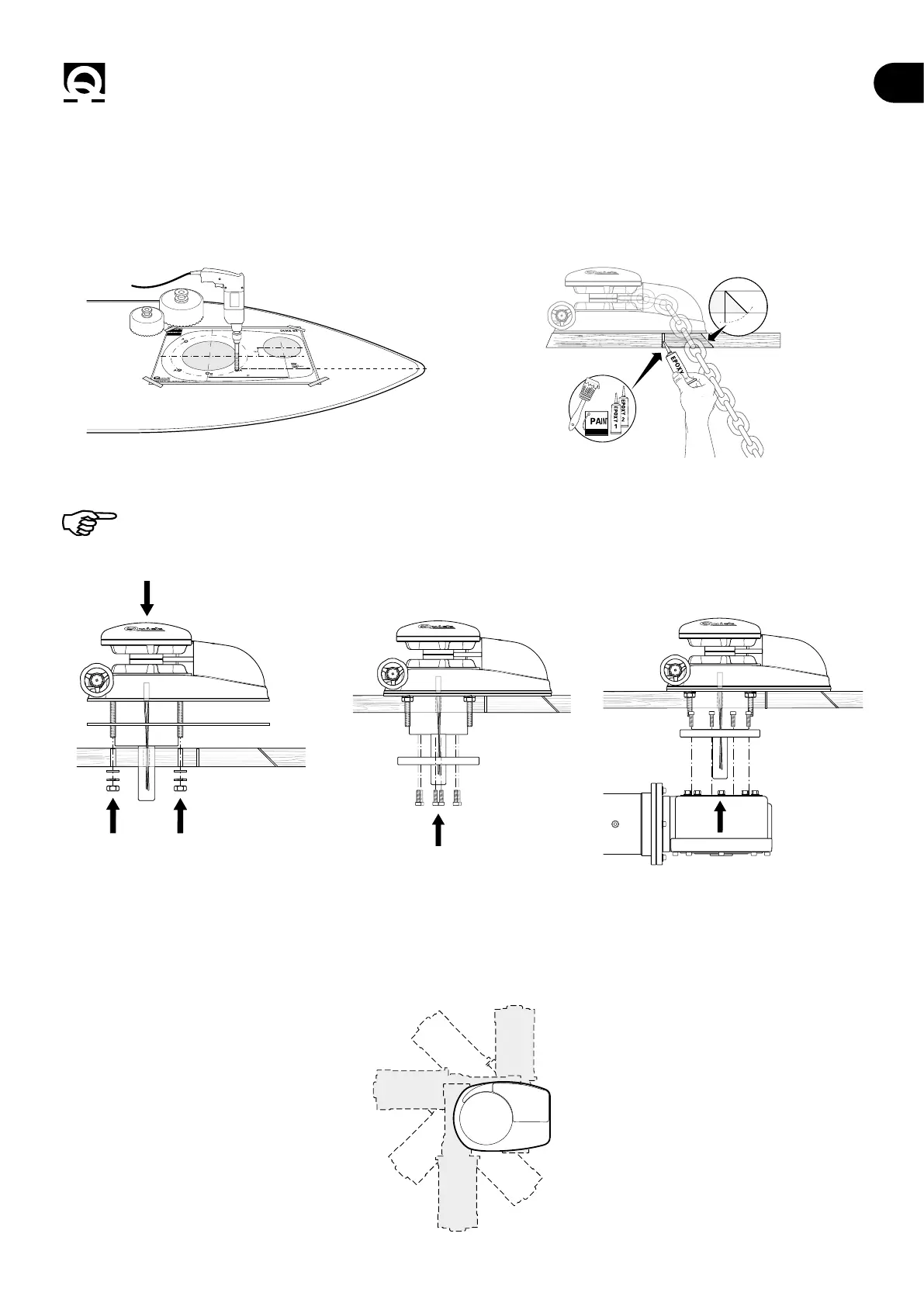
4.1 - Installation procedure
Identify the ideal position and drill the holes using the drilling template supplied.
Remove the excess material from the chain/rope passage hole, nish it and smooth it with a specic product (marine paint,
epoxy resin or gel) ensuring the free passage of the chain/rope.
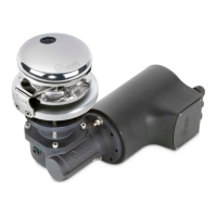
Position the upper part, inserting the gasket between the deck and the base (g.3), t the motor gearbox ange (g.4) and
connect the gearbox to it, inserting the shaft into the gearbox (g.5).
Fix the windlass by screwing the nuts onto the xing studs. (See tightening torque, ch.1.1 page 5).
FIG.3 FIG.4 FIG.5
ELECTRIC MOTOR: Connect the supply cables from the windlass to the remote switch/reversing contactor unit.
(see wiring diagram on page 9 to 11)
HYDRAULIC MOTOR: Connect the pipes coming from the distribution valve to the two hydraulic motor anges. (see
connection diagram on page 12)
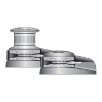
4.2 - Motor gearbox position
Depending on the type of motor gearbox, a
rotation every 45° or 90° is possible.