16
OPERATING
GB
CONTROL SIGNALS (ONLY SBC 250 ADV PLUS)
The battery charger has a 9-pin female connector (connector DB9, see fig..4) on which the analog signals
can be seen and used to monitor and control the equipment.
BASIC STATE OF BATTERY CHARGER
DESCRIPTION
Positive MASTER output (650mA max). By drawing 100mA the error is less than 0.7%.
Positive SLAVE A output (650mA max). By drawing 100mA the error is less than 0.7%.
Not connected or if it present, positive SLAVE B output (650mA max). By drawing 100mA the error is less
than 0.7%.
Basic state of battery charger (20 mA max).
Battery charger total current positive shunt (10 mA max). The transduction ratio is 100mV/100A.
GND signal 1 (V master).
GND signal 2 (V slave A).
GND signal 3 (V slave B, if it present).
Battery charger total current negative shunt.
CONNECTION PIN 4
HIGH IMPEDENCE
+ V CHARGE
STATE
OFF or PROBLEMS
ON WITH PROBLEMS
For a wiring example of control signals look at figure 3b.
NO.
1
2
3
4
5
6
7
8
9
The position and description of the signals on the connector are listed below.
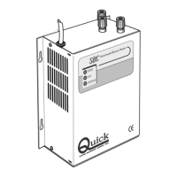
CHARGE
POWER
FLOAT
CHARGE
POWER
FLOAT
12345
6789
CONTROLL PANEL
LED
CONTROLL SIGNAL
CONNECTOR
FIG. 4
SLAVE A MASTER