40
FUNCIONAMIENTO
E
ESTADO SIMPLIFICADO DEL CARGADOR DE BATERÍAS
CONEXIÓN PIN 4
ALTA IMPEDANCIA
GND
ESTADO
APAGADO O PRESENCIA DE PROBLEMAS
ENCENDIDO O AUSENCIA DE PROBLEMAS
SEÑALES DE CONTROL (SÓLO SBC 250 ADV)
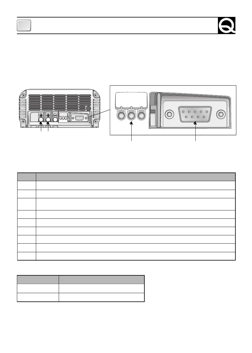
El cargador de baterías está equipado con un conector a 9 polos hembra (conector DB9, ver Fig. 4) en el
cual se indican las señales analógicas que pueden utilizarse para la monitorización y el control del equipo.
DESCRIPCIÓN
Positivo salida MASTER (650mA máx). Extrayendo 100mA el error es inferior al 0.7%.
Positivo salida SLAVE A (650mA máx). Extrayendo 100mA el error es inferior al 0.7%.
No conectado o bien, si presente, positivo salida SLAVE B (650mA máx). Extrayendo 100mA el error es
inferior al 0.7%.
Estado simplificado del cargador de batería (salida open collector, 20 mA máx.).
Positivo shunt corriente total cargador de baterías (10 mA máx). La relación de transducción es 100mV/100A.
GND señal 1 (V máster).
GND señal 2 (slave A).
GND señal 3 (V slave B, si presente).
Negativo shunt corriente total cargador baterías.
Un ejemplo de conexión de las señales de control se ilustra en la figura 3b.
NÚMERO
1
2
3
4
5
6
7
8
9
A continuación se indica la posición y la descripción de las señales presentes en el conector:
CHARGE
POWER
FLOAT
CHARGE
POWER
FLOAT
12345
6789
LED
TABLERO DE CONTROL
CONECTOR
SEÑALES DE CONTROL
FIG. 4
SLAVE A MASTER