25
GB
SBC NRG HIGH POWER - REV001A
OPERATION
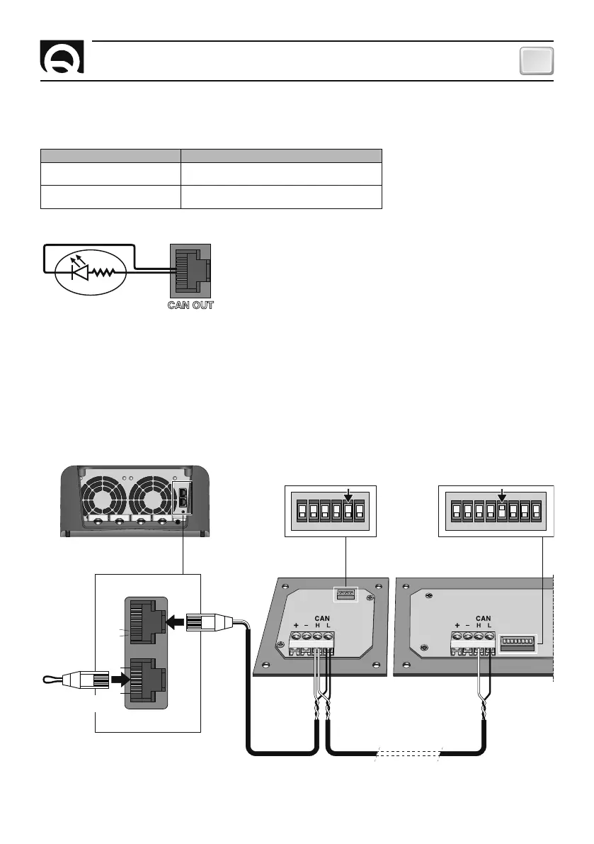
CAN BUS NETWORK CONNECTION - SINGLE BATTERY CHARGER
When making the data interface connection (CANH and CANL signals) use an unscreened cable with a twisted pair
(cross-section 0.25/ 0.35 mm
2
AWG 22/24, impedance 100/150 ohm). The maximum total length of the data signal
cable should be no more than 100 m. Activate the terminator at the first and last device connected to the network. If
there is only one device, the terminator does not need to be present.
Alternatively, you can use UTP CAT 5 ethernet patchcords with pre-arranged terminals.
An example of a network connection is given below:
CAN IN
CAN OUT
1234
ON
1234567 8
ON
1234567 8
ON
1234567 8
ON
123456
1234
ON
123456
CAN IN
CAN OUT
2
1
8
1
2
8
1
1
SBC NRG
TERMINATION
DEACTIVATED
TERMINATION
ACTIVATED
DIP-SWITCH
RDS
1521*
RDS
1541*
DIP-SWITCH
TERMINATION
CONNECTOR
* Optional devices.
CAN OUT
445
5
FIG. 4
PIN 4 CAN OUT CONNECTION STATE
HIGH IMPEDENCE
Battery charger switched off or presence of problems
requiring manual reset.
+ V OUTPUT
Battery charger switched on and absence of any
problem requiring manual reset.
BATTERY CHARGER’S SIMPLIFIED STATUS
On pin 4 of the RJ45 CAN OUT socket, a signal which indicates the operating status of the battery charger (presence or
absence of problems) is located (Fig. 4).
 Loading...