16
EN
TCD1022 E / 1042 E - REV005A
ELECTRIC CONNECTIONS
The control panel complies with EMC standards (electromagnetic compatibility) but requires correct installation to avoid com-
promising its performance and that of the surronding instruments.
For this reason the interface wires must be positioned at a distance of at least:
• 1 m away from cables that transmit radio signals (except for SSB radio transmitters).
• 2 m away from cables for SSB radio transmitter signals.
Follow the rules below to construct the electrical installation relative to the control panel:
• Connect the controls connector to the connector coming from the thruster.
• Put in a switch to turn on and shut off the instrument (not supplied).
• Position the switch so that it is within easy reach should it be necessary to shut off the instrument in an emergency.
• Insert a 4A quick-acting fuse on the controls power supply line (not supplied).
• Use wires, for the remote control power supply, with a correct cross section according to their length.
• Do not use voltage from the motor or thruster battery circuit for the control panel.
• Before switching on the power to the control, check that all the electrical connections are correct.
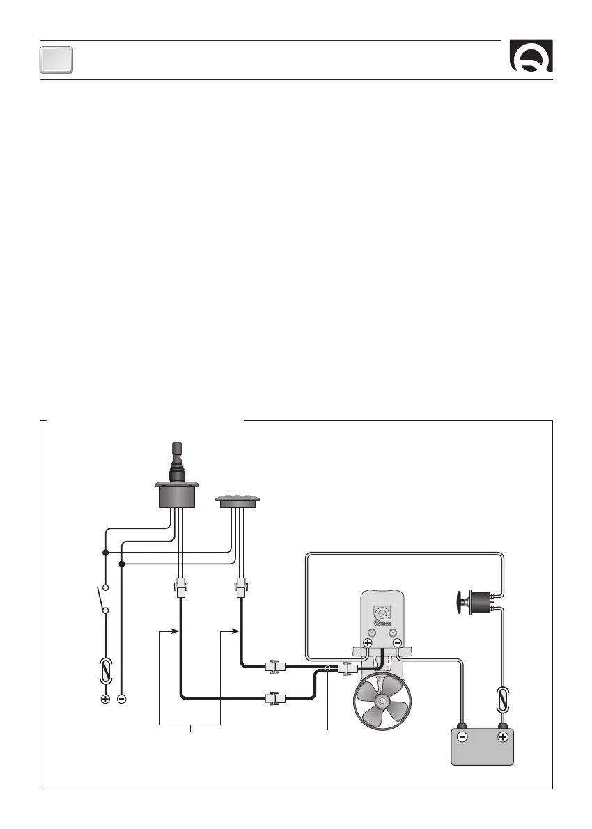
ELECTRICAL CONNECTIONS DIAGRAM
FUSE
TCD 1042
BATTERY
12/24 V
TCD 1022
RED
BLACK
RED
BLACK
SPLITTER
(OPTIONAL)
CONTROL CABLE
EXTENSIONS
(OPTIONALS)
MOTOR
TO THE SERVICE
BATTERY
BATTERY ISOLATOR
SWITCH
FUSE
*
*
*
Common negative for the battery groups.
INSTALLATION