EasyManua.ls Logo

Quicksilver 88688A25 - User Manual

Quicksilver 88688A25
12 pages
Print Icon
To Next Page IconTo Next Page
Loading...
88688A25
SINGLE HANDLE
TRIM CONTROL
INSTALLATION,
OPERATION AND
MAINTENANCE
INSTRUCTIONS
NOTICE to INSTALLER
After Completing Installation, These Instruc-
tions Should Be Placed with the Product For
the Owners Future Use.
These installation instructions provide complete in-
formation for installing the remote control. Please read
c
them carefully and thoroughly before starting installa-
tion.
24906
Index
Page
Notice to Installer/Owner
........................
2
Maintenance and Replacement Parts
.............
2
Selecting Remote Control Cables
.................
2
Introduction
....................................
3
Installation......................................
3
Remote Control Alteration for Port Installation
....
4
Control Module Linkage
......................
4
Control Handle
...............................
4
Repositioning Control Handle
....................
5
Starboard Side Control Module Cable
Installation
...................................
7
All Outboard Models thru 250 (3 Litre)
...........
7
Shift Cable
...................................
7
Throttle Cable
................................
7
Port Side Control Module Cable Installation
.......
8
All Outboard Models 35 hp thru 220 hp
........
8
Shift Cable
...................................
8
Throttle Cable
................................
8
Required Mounting Clearances
...................
9
Locating and Drilling Mounting Area
..............
9
Remote Control Mounting
.......................
9
Electrical Connections
..........................
10
Operation.
.....................................
11
Printed in U.S.A.
1-
go-812627
l-195
Question and Answer IconNeed help?

Do you have a question about the Quicksilver 88688A25 and is the answer not in the manual?

Summary

Notice to Installer;Owner

Maintenance and Replacement Parts

Selecting Remote Control Cables

Introduction

Installation

Final Checks and Adjustments

Perform final checks on handle tightness, cable routing, and adjust detent and friction for smooth operation.

Remote Control Alteration for Port Installation

Control Handle Features

Starboard Control Mounting

Port Control Mounting

Repositioning Control Handle

Starboard Side Control Module Cable Installation

Shift Cable Connection

Connect the shift cable to the control module using specified fasteners and torque.

Throttle Cable Connection

Connect the throttle cable to the control module using specified fasteners and torque.

Port Side Control Module Cable Installation

Shift Cable Connection

Connect the shift cable to the control module for port side installation, ensuring proper fastener torque.

Throttle Cable Connection

Connect the throttle cable to the control module for port side installation, ensuring proper fastener torque.

Required Mounting Clearance

Locating and Drilling Mounting Area

Remote Control Mounting

Electrical Connections

Operation

Control Handle Operation

Understand control handle travel for shifting gears and advancing throttle for smooth operation.

Throttle Only Button Function

Utilize the throttle-only button for engine throttle advancement when in neutral for starting.

Control Handle Tension Adjustment

Adjust detent and friction screws to achieve desired control handle tension and feel.

Trim;Tilt Switch Operation

Operate the trim/tilt switch to adjust the power trim position of the outboard motor.

Overview

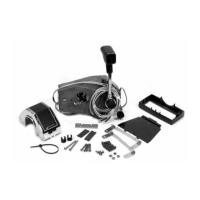
The device described in the manual is a Quicksilver 88688A25 Single Handle Trim Control for marine applications, designed to provide complete one-hand operation of both shift and throttle functions. It is intended for console mounting and is compatible with various outboard models.

Function Description:

The primary function of this device is to control the shift and throttle of an outboard engine, as well as the power trim/tilt. It integrates these functions into a single handle for ease of use. The control is equipped with a neutral start switch, which is a critical safety feature designed to prevent accidental in-gear starting of the engine. The first approximately 40 degrees of control handle travel from the neutral position engage the gears (forward or reverse), while the remaining travel advances the throttle. A "Throttle Only Button" allows for engine throttle advancement without shifting gears, useful for starting the engine. The trim/tilt switch, located on the handle, allows the user to trim the power package "UP" (out) or "DOWN" (in).

Important Technical Specifications:

  • Torque Specifications:
    • Control handle set screw: 60 lb. in. (7 N.m)
    • Cable end guide set screws: 20 to 25 lbs. in. (2.3 to 2.8 N.m)
    • Shift cable fastener locknut: 20 to 25 lb. in. (2.3 to 2.8 N.m)
    • Throttle cable fastener locknut: 20 to 25 lb. in. (2.3 to 2.8 N.m)
    • Access cover and cable retainer screws: 60 lb. in. (7 N.m)
    • Back cover screws (for port installation alteration): 60 lb. in. (7 N.m)
    • Remote control mounting screws: Four 1-1/2" (38mm) long screws.
  • Cable Requirements: Quicksilver throttle and shift control cables are recommended. Cables must be the correct length to avoid kinks or excessive loops, which can stress the cables.
  • Mounting Clearance:
    • Hand clearance: 2 inches (50.8mm)
    • Minimum cable bend radius: 12 inches (30.5cm)
    • Cables should extend straight downward for at least 3 ft. (1m) before bending.
  • Power Trim Compatibility: This trim control is designed to connect only to Power Trims equipped with a 2-solenoid trim pump. If the Power Trim has only one solenoid, a Trim Solenoid Kit must be purchased and installed.
  • Wiring: Neutral start safety switch leads must be connected properly to prevent in-gear starting. Wiring harnesses should be secured every 18" (45.7cm) and kept away from water and potential pinch points.

Usage Features:

  • Single Handle Operation: Provides intuitive control of shift, throttle, and trim/tilt from one handle.
  • Neutral Start Switch: A safety interlock that prevents the engine from starting unless the control handle is in the neutral position.
  • Throttle Only Button: Allows for engine warm-up or starting without engaging the gears. This button can only be depressed when the control handle is in neutral.
  • Control Handle Friction Adjustment Screw: Allows the user to adjust the tension of the control handle to their desired feel (clockwise to increase tension, counterclockwise to decrease).
  • Control Handle Detent Tension Adjustment Screw: Allows the user to adjust the tension of the detents (gear engagement points) for a firmer or lighter feel (clockwise to increase tension).
  • Trim/Tilt Switch: Integrated into the handle for convenient power trim and tilt adjustments.
  • Port/Starboard Installation: The control can be configured for either starboard (right-hand) or port (left-hand) installation by altering the internal throttle link and spring, and repositioning the trim switch within the handle.
  • Repositioning Control Handle: The control handle's neutral position can be adjusted on the control shaft if the standard neutral position is undesirable, ensuring full forward and reverse travel can still be achieved.

Maintenance Features:

  • Regular Inspections:
    • Check fasteners securing the remote control to the boat for tightness.
    • Check set screws securing control handles to the remote control for tightness (60 lb. in. / 7 N.m).
    • Check electrical connections for tightness and proper securing away from bilge water.
    • Check throttle and shift cables for tight set screws in cable end guides (20 to 25 lbs. in. / 2.3 to 2.8 N.m).
  • Lubrication:
    • Annual inspection and lubrication of the remote control assembly, or whenever operating effort increases. Lubricate with Quicksilver 2-4-C Marine Lubricant or equivalent.
    • Lubricate shift and throttle cable lubrication points with Quicksilver 2-4-C Marine Lubricant.
  • Service Intervals:
    • Normal Service: Every 50 hours of operation or 60 days (whichever comes first).
    • Severe Service: Every 25 hours of operation or 30 days (whichever comes first). "Severe Service" is defined as operation in a salt water area.
  • Cable Routing: Emphasizes correct cable routing to prevent binding, kinks, or excessive stress, which can lead to hard shifting or binding throttle action.
  • Protective Sleeve: A protective sleeve must be positioned over the wiring harness behind the mounting bracket to prevent wires from being pinched or cut.

The manual provides detailed instructions for installation, including mounting clearances, cable routing, electrical connections, and specific steps for altering the control for port installation or repositioning the control handle. It also includes important safety alerts (DANGER, WARNING, CAUTION) to highlight potential hazards and ensure safe operation and maintenance.

Quicksilver 88688A25 Specifications

General IconGeneral
BrandQuicksilver
Model88688A25
CategoryMarine Equipment
LanguageEnglish