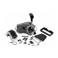
7. Rotate trim wires and trim wire rotator (on control
shaft) to the position that neutral is desired when
control handle is reinstalled.
50092
a
-
Trim Wires and Rotator
b
-
Spacer Disc
c
-
Standard Position of Trim Wires and Rotator
d
-
If Trim Wires and Rotator Are Moved to This Angle (or Any
Other Angle) from the Standard Position, the Control Handle
Must Also Be Installed (on Control Shaft) in the Same Angle
(thus Neutral is Changed to This Angie from Standard Neutral
Position)
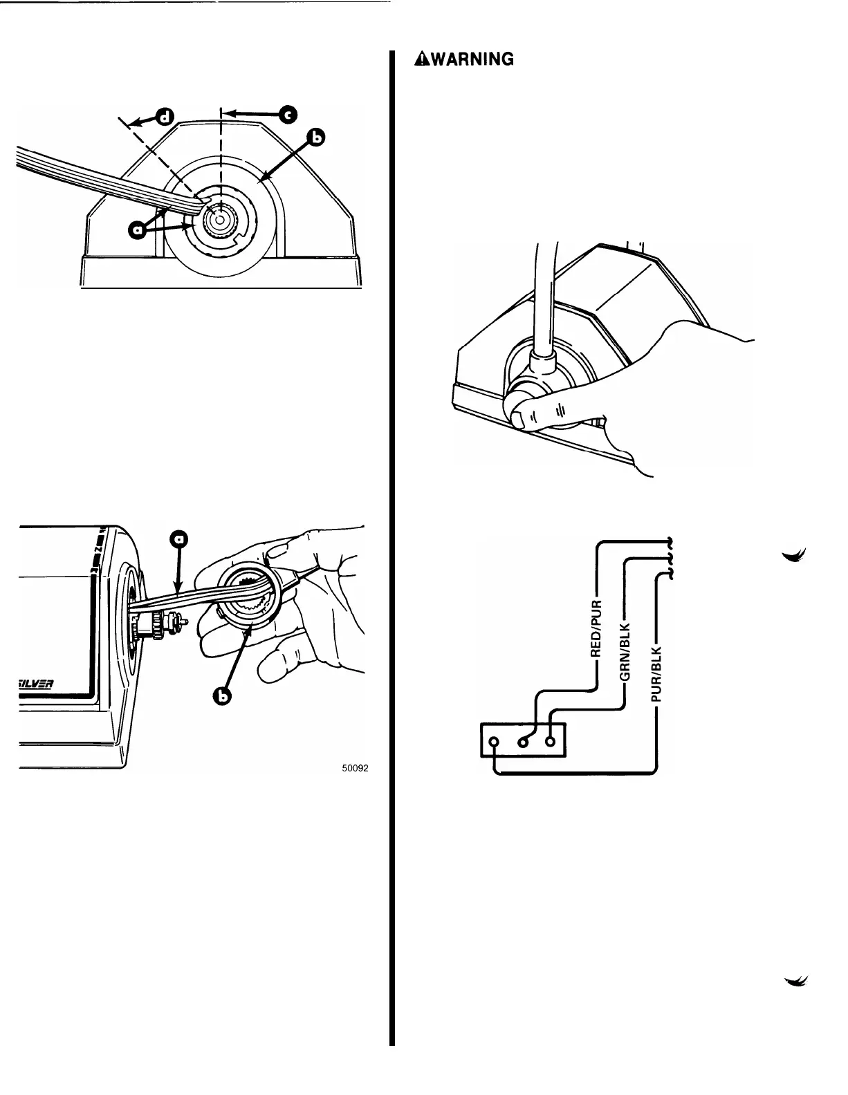
8. Reinstall handle to control shaft (make certain full
forward and full reverse can be achieved) at desired
location.
a
-
Trim Wires
b
-
Control Handle
AWARNING
Control handle set screw must be torqued to specifica-
tion. Failure to tighten set screws securely could allow
control handle to disengage, with subsequent loss of
throttle shift control.
9. While holding in on hub of control handle, move
handle until access to set screw is achieved. Torque
control handle set screw to 60 lb. in. (7 N.m).
10. Push the “Throttle-Only” button onto control shaft.
\
50063
11.
Reconnect trim wires to terminals on trim switch.
50091
12. Place trim switch into handle and install trim switch
retainer/cover onto handle.
13.
Reconnect trim wire connection to ignition switch
connection.
-6-