Do you have a question about the Quietside DPW-099A and is the answer not in the manual?
Steps and checks required before operating the appliance.
Important cautions and procedures to follow during normal appliance operation.
Guidelines to prevent freezing damage to the appliance and pipes during cold weather.
Procedures for short-term non-use, including activating freeze protection.
Instructions for safely shutting down and storing the unit for extended periods.
Detailed steps for operating the unit in closed loop heating mode.
Guide on setting the repeated timer function for cyclical heating operation.
Instructions for setting and using the domestic hot water function.
Specific steps for supplying water using the pressure gauge and air close type system.
Actions to take if a gas smell is detected, including checking for leaks and contacting service.
What to do if exhaust fumes are smelled, indicating potential poisoning risk.
Troubleshooting steps for when the appliance fails to ignite properly.
Identifying and resolving unusual noises the appliance might make during operation.
Steps to diagnose and fix issues where the room is not heating adequately.
Troubleshooting steps when domestic hot water supply is interrupted or unavailable.
An exploded view showing the various components of the appliance.
Identifies error code A2 related to fan motor issues and provides troubleshooting steps.
Addresses error code A3 concerning the pump detection switch status before operation.
Explains error code A4 caused by overheat thermostat opening and potential solutions.
Details error code A5 related to the pump detection switch status during operation.
Describes error code A6 indicating ignition failure and troubleshooting for gas supply and ignitor.
Covers error code A7, which signifies a stuck gas valve relay, pointing to PCB issues.
Explains error code A8 for pseudo flame detection, indicating potential gas control valve or PCB problems.
Details error code A9 related to freeze prevention operation, suggesting pipe insulation.
Addresses error codes Ab and Ac for thermostat abnormalities in heating and DHW systems.
Explains error code AA for prevention of boiling, with troubleshooting for valves, filters, pumps, etc.
Covers error code Ad indicating blockage in the condensate or flue system, recommending cleaning.
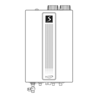
Step-by-step instructions for securely attaching the appliance to the wall.
Key considerations and warnings for correctly installing the vent terminal outdoors.
Illustrates the standard and recommended configuration for the appliance's venting system.
Detailed instructions for drilling holes, measuring, and inserting vent pipes.
Presents alternative venting configurations, including non-direct, snorkel, and concentric types.
Summarizes maximum vent lengths and general precautions for safe and effective venting.
Provides guidance on selecting appropriate gas pipe sizes based on distance and gas type.
Tables showing maximum capacity for natural gas supply based on pipe size and length.
Tables showing maximum capacity for propane gas supply based on pipe size and length.
Instructions for safely shutting off the gas supply to the appliance before servicing.
Critical safety information to review before operating the appliance for the first time.
Configuration settings for the dip switches when operating with natural gas.
Configuration settings for the dip switches when operating with LP gas.
How to access and modify unit options, such as temperature display units.
Instructions for setting up zone control functionality for the appliance.
How to lock the unit into its maximum firing rate for specific purposes.
How to lock the unit into its minimum firing rate for specific purposes.
Specific venting requirements mandated for installations in Massachusetts.
Details the manual fill valve for the closed loop system and its operation.
Explains how zone control is performed via zero voltage or X-X contacts.
Describes the DSR-100F controller's function and how it interfaces with zoning.
| Brand | Quietside |
|---|---|
| Model | DPW-099A |
| Type | Tankless |
| Fuel Type | Propane |
| Water Flow Rate | 9.9 GPM |
| Ignition Type | Electronic |
| Venting | Direct Vent |
| Minimum Water Flow | 0.5 GPM |
| Maximum Inlet Water Pressure | 150 PSI |
| Heating Capacity | 199, 000 BTU/hr |