QR-25 Series Quincy Compressor
52201-107, December 2012 11 3501 Wismann Lane, Quincy IL - 62305-3116
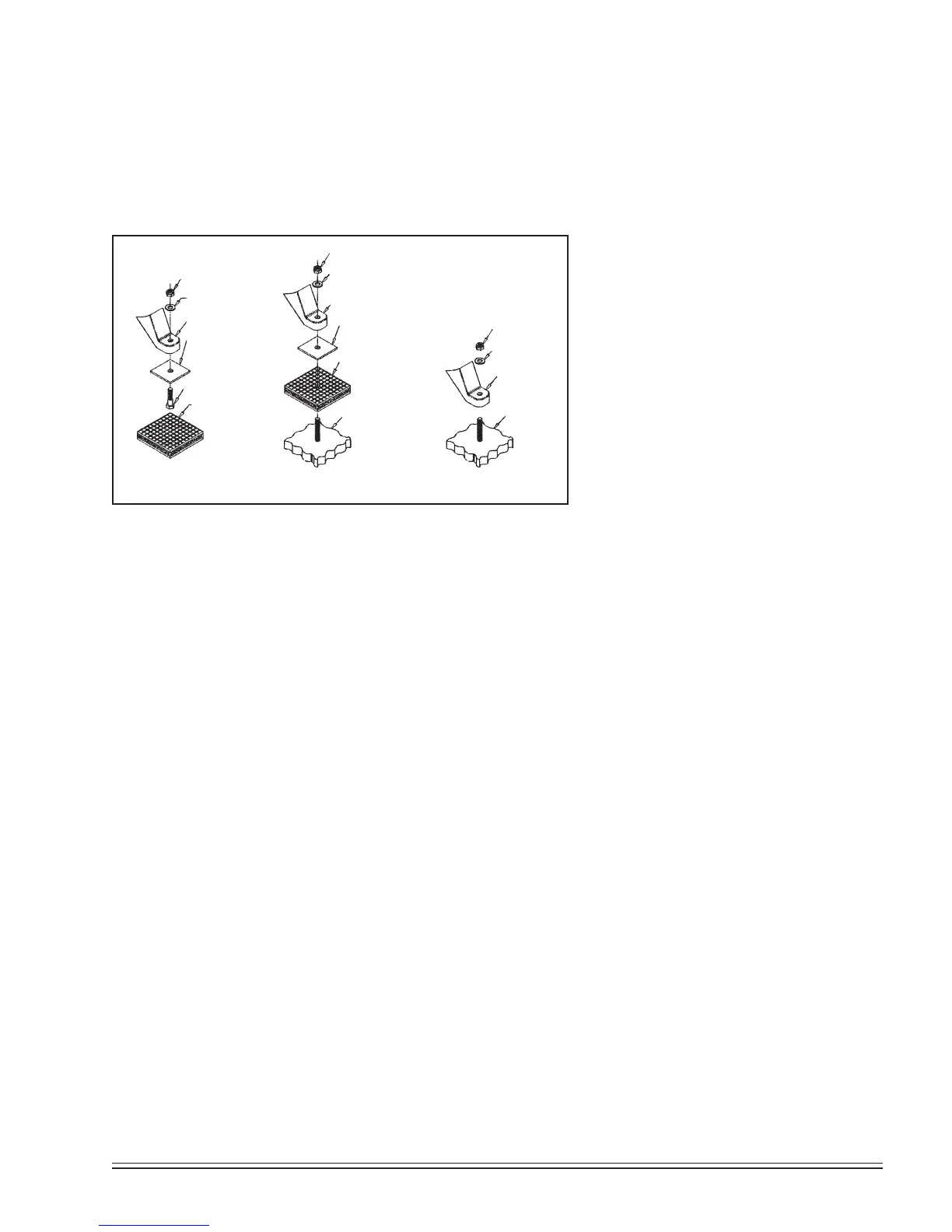
HORIZONTAL TANK UNITS
ANCHORED
VERTICAL TANK UNITS
ANCHORED
HORIZONTAL TANK UNITS
UNANCHORED
1/2” locknut
1/2” at washer
tank foot
isolator backing plate
1/2” x 2” bolt
isolator
1/2” locknut
1/2” at washer
tank foot
isolator backing plate
isolator
1/2” oor stud
(provided by customer)
1/2” oor stud
(provided by customer)
tank foot
1/2” locknut
1/2” at washer
Fig. 3-1 Isolator Installation for
Unanchored or Anchored Receivers
Mounting
Proper mounting of Quincy compressor units is crucial to the safe operation
and longevity of the equipment. The installation requires a flat and level
concrete floor or pad (for mobile units see Mounting Mobile Units). Satis-
factory results can usually be obtained by mounting horizontal tank units on
vibration isolators available from your local Quincy distributor. All vertical
tank units must be anchored! Quincy recommends that all vertical tank
units be mounted as indicated without
isolators. Refer to Fig. 3-1, Isolator Instal-
lation for Unanchored or Anchored
Receivers.
State or local codes may mandate that
the unit be bolted to the floor. In this case
the unit must be leveled and bolted making
absolutely certain the feet are not stressed
in any manner. Leave the locknut loose!
Uneven feet drawn tightly to the concrete
pad will cause severe vibrations resulting
in cracked welds or fatigue failure. The
customer is responsible for pro viding a
suitable foundation & isolator mounting
where necessary.
Mounting Mobile Units
Units mounted to truck beds should be fas tened in such a way so as not to
create any stress to the air receiver tank. Truck beds, characteristically, have
a tendency to flex and could cause damage to the receiver tank if the tank is
fastened directly to the truck bed. It is the User’s responsibility to provide an
adequate means of fas tening the unit in these applica tions.
Do not operate this compressor more than 15° off level or move it
while it is operating.
System components
Efficiency and safety are the primary concerns when selecting compo nents
for compressed air systems. Products of inferior quality can not only hinder
performance of the unit, but could cause system failures that result in bodily
harm or even death. Select only top quality compo nents for your system. Call
your local Quincy distributor for quality parts and professional advice.
Drive Pulleys / Sheaves
Various pulley and sheave combinations are available to obtain the de sired air
pressure and delivery rate of your compressor. Consideration must be given
to these combinations to ensure that the motor is not over loaded by operating
above or below the designed speed range.
Whatever combination is employed, the drive pulleys & com pressor sheaves
must be properly aligned and drive belt tension set to specifica tions (refer to
SECTION 5, Pulley / Sheave Alignment & Belt Tension). Improper pul-
ley/sheave alignment and belt ten sion can cause motor overloading, excessive
vibration, and prema ture belt and/or bearing failure.
CAUTION !
 Loading...