QR-25 Series Quincy Compressor
52201-107, December 2012 4 3501 Wismann Lane, Quincy IL - 62305-3116
SECTION 2 SYSTEM DYNAMICS
Description & Applica-
tion
The Quincy Compressor QR-25
Series consists of heavy duty
indus trial, belt driven, single or
two stage compressors. Single
stage compressors are capable
of delivering up to 100 PSIG
continuously. Some single
stage compressors are capable
of delivering up to 150 PSIG
intermittantly (with proper
controls and modifica tions). Two
stage compressors can deliver
up to 200 PSIG contin uously,
and up to 250, 350 or 500 PSIG
intermittently depending upon
the model, controls and configu-
ration.
Principles of Compres-
sion Cycles
Single Stage Compressors
During the downstroke of a
single stage compressor, air is
drawn through an intake valve
in the head of the compressor
and into the cylinder. At the
bottom of the stroke, the intake
valve closes and air is trapped in the cylinder. The air is then compressed
in the cylinder during the upstroke of the piston. Total compression, from
atmo spheric pressure to the final discharge pressure, is accomplished in one
stroke of the piston.
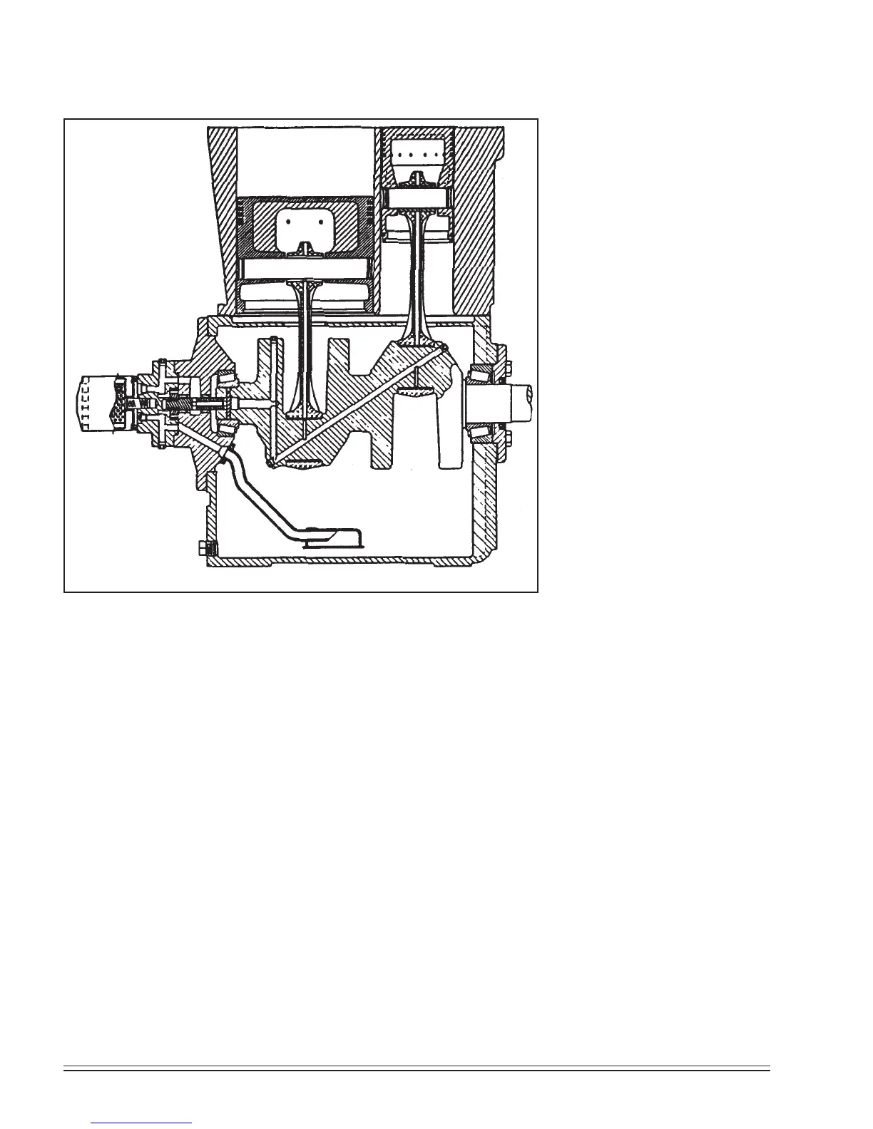
Two Stage Compressors
During the downstroke of the piston of a two stage compressor, air is drawn
through an intake valve in the head of the compressor into the low pressure
cylinder and compressed during the upstroke of the piston.
The compressed air is then released through a discharge valve in the head
of the compressor to an intercooler (usually finned tub ing) where the heat
resulting from compression is allowed to dissipate. The cooler compressed air
is then drawn into a second compression cylinder, the high pressure cylinder,
for compression to final pressure.
From there the compressed air is released through a discharge valve to an
air receiver tank or directly to a network of compressed air supply lines. In
one revolution of the crankshaft a compression cycle is completed.
Fig. 2-1 Cross Section of Typical QR-25
2 Stage Pressure Lubricated Cylinder & Crankcase
Pix 1064
 Loading...