-
-
-
-
-
-
-
SECTION
5.
CORRECTIVE
MAINTENANCE
5.1
INTRODUCTION
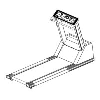
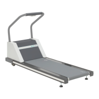
The Q55/Q65 Medical Treadmill
is
designed
to
operate
without scheduled
maintenance.
The
procedures
in
this
section
are
needed for
correct
ive
maintenance.
Repair
and
replacement
procedures
include disassembly
and
reassembly
procedures
and
are
included in
Section
5.2. Adjustment and alignment
procedures
are
included in
Section
5.3 and
calibration
procedures
are
included in Section
5.4.
Section
5.5
is
a
post-maintenance
test.
Refer
to
Section
3 for theory
of
operation
and
Section
4
for
troubleshooting procedures.
The following
precautions
should
be
observed
whenever Q55/Q65
maintenance
is
performed:
1. Do
not
start
the
walking
belt
when
anyone
is
on
the
belt.
2.
If
the
treadmill
shuts
itself
off
for any
reason,
remove
the
patient
from
the
walking
belt
immediately.
3. To
prevent
high voltage
electrical
shock,
unplug
the
treadmill
any
time
you remove
the
hood.
4.
Do
not
wear loose
clothing
around
rotating
machinery.
5.
High voltage
is
present
when
the
treadmill
hood is removed and
the
treadmill
is
plugged in.
5.2 DISASSEMBLY AND REASSEMBLY
PROCEDURES
This
section
contains
procedures
for Q55/Q65
disassembly, component
replacement
and
reassembly. Because
PCB
components
are
not
field repa irable, no procedures
are
included
for
PCB
component
repair
or
replacement.
Section
5.2.1
contains
procedures
to
replace
components
that
are
easily
accessible
under
the
treadmill
hood. Sections 5.2.2 and 5.2.3
contain
procedures
for
input and
output
shaft
disassembly and reassembly.
Section
5.2.4
contains
procedures
to
replace
the
rack
gears
and pinion
shaft.
Section 5.2.5 and 5.2.6
contain
procedures
to
replace
belt
tracking
switches,
the
walking
belt,
and
drive .and idler
pulleys.
5.2.1 Access Under
the
Treadmill Hood
1.
Unplug
the
treadmill
from
the
wall
outlet.
2.
Re move
the
front
handrail.
3. Remove
the
four
bolts
holding
the
hood
to
the
treadmill.
4.
Lift
the
hood
straight
up
off
the
treadmill.
5.2.1.1 Drive
Motor
2M2 Replacement
Drive motor
2M2
requires
replacement
when
the
internal
thermal
overload
protector
or
motor
start
switch fails
or
when
the
motor
burns out.
1.
Take
grade
to
approximately
10%.
2.
Perf
orm
the
procedure
in
Section
5.2.1.
3. Remove
the
cable
ties
to
connector
2AIP6 and unplug
connector
2AIP6.
4.
Disconnect
the
two
wires from
contactor
2K
1 by removing
the
screws.
5. Remove
the
four bolts
that
hold
the
motor in place.
6.
Remove
the
drive
motor.
7.
Replace
with a new drive motor in
reverse
order
of
disassembly.
Refer
to
drawing number 0208-201 (Q55)
or
0221-201
(Q65) for wire
arrangement.
8.
Wi
th
the
treadmill
unplugged,
replace
the
hood and handrail.
5.2.1.2 Speed Change
Motor
2A2
Replacement
Speed change motor
2A2
requires
replacement
if
the
gears
break
or
if
the
motor burns out.
1.
Perform
the
procedure
in
Section
5.2.1.
2.
Remove
the
cable
ties
from
the
quick
disconnect
to
the
speed change motor.
3. Disconnect
the
quick disconnect from
the
5-1
 Loading...