-
2.
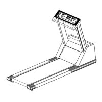
Unplug
the
treadmill, remove
the
handrail
R.nd
lift
the
hood
straight
up
off
the
treadmill.
Exercise
caution
to
avoid damage
to
bearings and
caps
on the
output
shaft.
If
the
output
shaft
is
scarred
or
if
the
moveable sheave is
frozen
on
the
output
shaft,
the
entire
shaft
assembly must be
replaced.
NOTE
A
replacement
output
shaft
assembly
can
be obtained from Quinton Medical
Company's
Service
Department.
3. Carefully remove
the
tachometer
optical
sensor
from
the
bearing
cap.
4. Remove
the
tachometer
beam chopper.
5.
Remove
the
speed change motor
by
removing
the
two bolts holding
it
to
the
bracket.
6.
With
an
air
wrench or a
ratchet
wrench
with a long extension, remove
the
four bolts
holding
the
beari
ng
caps
in place.
7.
Take a rope
or
flexible
belt
and put
it
around
the
variable speed
belt.
Pull
straight
up
to
loosen
the
belt.
Figure
5-1
illustrates
the
loosening
of
the
variable speed
belt.
8.
Remove
the
output
shaft
assembly.
5.2.3.1 Output Shaft Assembly Replacement
1.
Perform
the
procedure in Section 5.2.3.
2.
Slip
the
variable speed
belt
onto
the
input
and
ou
tput
pulleys.
3.
Install an undamaged
output
shaft
by
replacing
the
bearing caps, narrow side down,
and
tightening
the
bolts with an
air
wrench
or
a
ratchet
wrench with a long extension.
4.
Install
the
speed change motor back onto
the speed change motor
bracket.
5.
Replace
the
tachometer
optical
sensor on
the
top
of
the
bearing
cap.
6.
Install
the
tachometer
beam chopper and
perform
the
alignment
in
Section 5.3.5.
7.
Unplug
the
treadmill
and
replace
the
hood
and handrail.
8.
Restore
power
to
the
treadmill
and
calibrate
speed (Section 5.4.1). Before
returning
the
treadmill
to
service,
ensure
that
the
treadmill
calibration
has been performed
on
the
Q2000 (Steps
1,
2 and 7
of
Section 4.4
of
the
Q2000 Service Manual)
or
the
645 PTC
(Section 6.2
of
the
645 PTC Technical Manual).
5.2.3.2
Replacement of a Seized Bearing
on
the Output Shaft
1.
Perform
the
procedure in Section 5.2.3.
2.
Inspect
the
shaft
for damage. If
the
shaft
is damaged,
obtain
a
replacement
output
shaft
and
replace
the
shaft
using
the
procedure
in
Section 5.2.3.1.
3.
Remove
the
bearing
cap
from
the
end of
the
shaft
using a
gear
puller or press.
Refer
to
Step
2
if
the
output
shaft
is damaged.
4. Remove
the
old bearing from
the
shaft
using a
gear
puller or press.
5.
Press
the
new bearing
onto
the
shafft
using
an
arbor
press.
6.
Apply
Loctite
Primer
T and
Loctite
RC
609
to
the
inside
of
the
beari ng
cap
and
replace
the
bearing cap.
7.
Replace
the
output
shaft
by
performing
steps
2 through 8
of
Section 5.2.3.1.
5.2.3.3
Reinstallation of a Loose Bearing
on
the Output Shaft
1.
Perform
the
procedure in Section 5.2.3.
2.
Carefully remove
the
loose bearing from
the
end of
the
shaft.
3. Inspect
the
output
shaft.
If
the
shaft
is
damaged,
obtain
a
replacement
output
shaft
assembly and
replace
the
shaft
using
the
procedure in
Section
5.2.3.1.
4. If
the
shaft
is
not
damaged,
perform
the
following.
5·7
 Loading...