16 quED Manual www.qutools.com
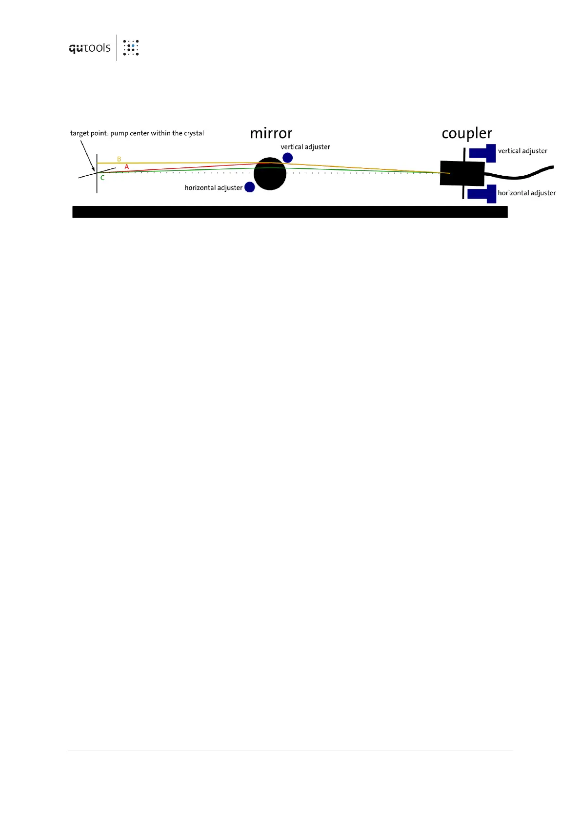
Figure 6: Walking procedure: In the beginning the beam points directly onto the target along
path A. The dotted line, however, is the path we are aiming for. To solve this situation, a vertical
walk has to be performed: turning (just a little bit) the vertical adjuster of the mirror alone leads
to path B. The displacement at the target has now to be compensated with the vertical adjuster
of the coupler to arrive at path C. The beam, again, points directly to the target, yet the path is
closer to the dotted line. Each time the procedure is repeated, the path comes closer to the
dotted line. Usually, one cannot tell directly whether the beam is above or below the dotted line
in the beginning and when the perfect path is reached. Therefore, one first has to try one
direction of walking and change the direction in case the signal gets worse (or end the
procedure when on a maximum). It is essential not to mix up vertical and horizontal directions
and to keep good track of the signal values and the direction of the steps already performed.
Angle alignment, aka walking: This kind of adjustment aims to manipulate the angle under
which a target is hit. For the quED this usually means the angle between the coupler mode and
the pump beam axis while the overlap with the target – the pump center – is already
established. This is a four DOF problem and can in principle concern the horizontal and or the
vertical direction. Unfortunately, walking has to be done iteratively. The procedure is explained
in Figure 6.
3.4.2 Realignment of the setup
After a prolonged time of storage or after shipping often a slight misalignment of the setup
only occurs. This, however, only requires realignment of the pointing (2 DOF) to reestablish the
overlap of pump and coupler modes within the crystal. The crucial setting for the entanglement
is the diagonal polarization measurement basis. Therefore, set the polarizers for +45° and +45°
(PP). Modify the pointing carefully for a maximum coincidence rate. Check the coincidence rates
for vertically- and horizontally- polarized pairs. These should be fairly similar but do not have to
be equal. When these two requirements are accomplished, maximum in PP and similar rates in
HH and VV, you can make a quick check of the entanglement quality to be expected as
described in 3.5.