EasyManua.ls Logo

RAB A17 - Slipfitter Mount Installation; Mounting and Securing; 0-10 V Dimmable Wiring; Wiring Connections

RAB A17
7 pages
Print Icon
To Next Page IconTo Next Page
To Previous Page IconTo Previous Page
Loading...
INSTRUCTIONS
A17™ AREA LIGHT INSTALLATION



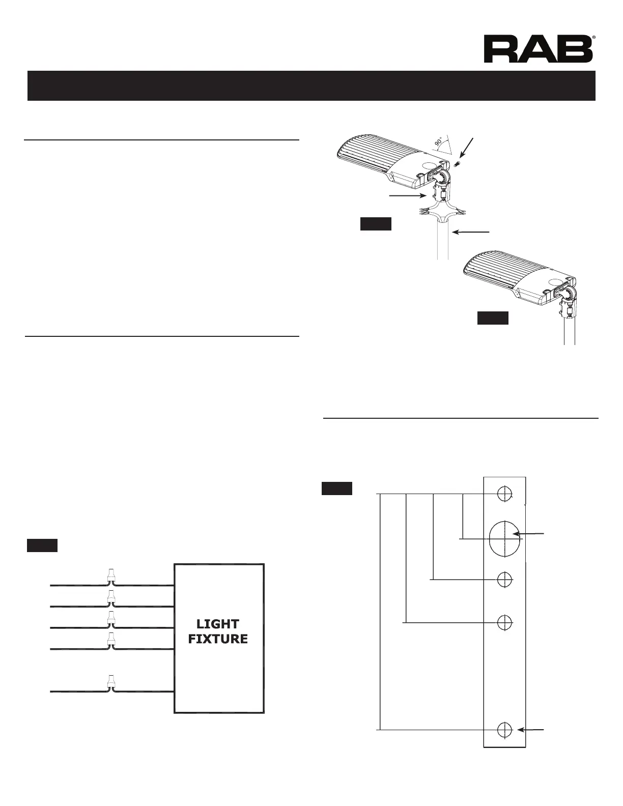
NOTICE: Adjustable angle is 90°.
1. Place the Slip tter over the Tenon and secure the Fixture
set ScrewsSlip tter
 Fixture through Slip tter
Slip tter and

 Slip tter, loosen the Locking Bolt
Fixture
Slip tter 
angle.
Figure 14
Note: These instructions do not cover all details or variations in equipment nor do they
provide for every possible situation during installation, operation or maintenance.




Fig. 7.
 
 
lead.
 


 
 
FIG. 5
FIG. 7
FIG. 6
BLACK/BROWNLINE
WHITE/BLUECOMMON
PURPLE(+) DIM V+
PINK
GREEN/YELLOW
(-) DIM V-
GROUND
Locking Bolt
Screws
Tenon

(Fig. 8).
Hole A B, C or D as needed.


0.625”
0.425”
5 1/2”
3”
2”
1”
A
B
C
D