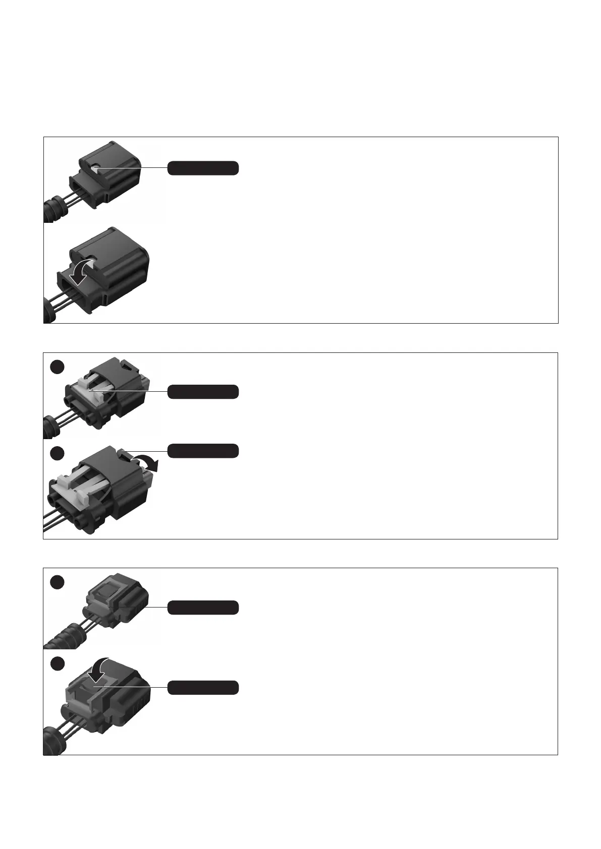
Locking clip
Locking clip 1
Locking clip 1
Locking clip 2
Locking clip 2
Detaching the connector correctly
The plugs are locked into the connection sockets by means of a locking
clip. Press the locking clip and pull the plug.
Because the plug is often connected very tightly to the socket, it is
helpful, when pressing the locking clip, to rst push the plug towards the
connection socket before subsequently pulling on it.
In addition, temperature uctuations in the engine bay can result in a type
of “vacuum effect” between the plug and the socket. This can be solved by
lightly “wiggling” the plug.
In the rst step, the orange locking clip 1 is pulled out. Press the black
locking clip 2, which functions as a lever for loosening the plug and pulling
it out.
Because the plug is often connected very tightly to the socket, it is
helpful, when pressing the locking clip, to rst push the plug towards the
connection socket before subsequently pulling on it.
In addition, temperature uctuations in the engine bay can result in a type
of “vacuum effect” between the plug and the socket. This can be solved by
lightly “wiggling” the plug.
In the rst step, the red locking clip 1 is pulled out. Press the black locking
clip 2, which functions as a lever for loosening the plug and pulling it out.
Because the plug is often connected very tightly to the socket, it is
helpful, when pressing the locking clip, to rst push the plug towards the
connection socket before subsequently pulling on it.
In addition, temperature uctuations in the engine bay can result in a type
of “vacuum effect” between the plug and the socket. This can be solved by
lightly “wiggling” the plug.
1
2
1
2
 Loading...