12
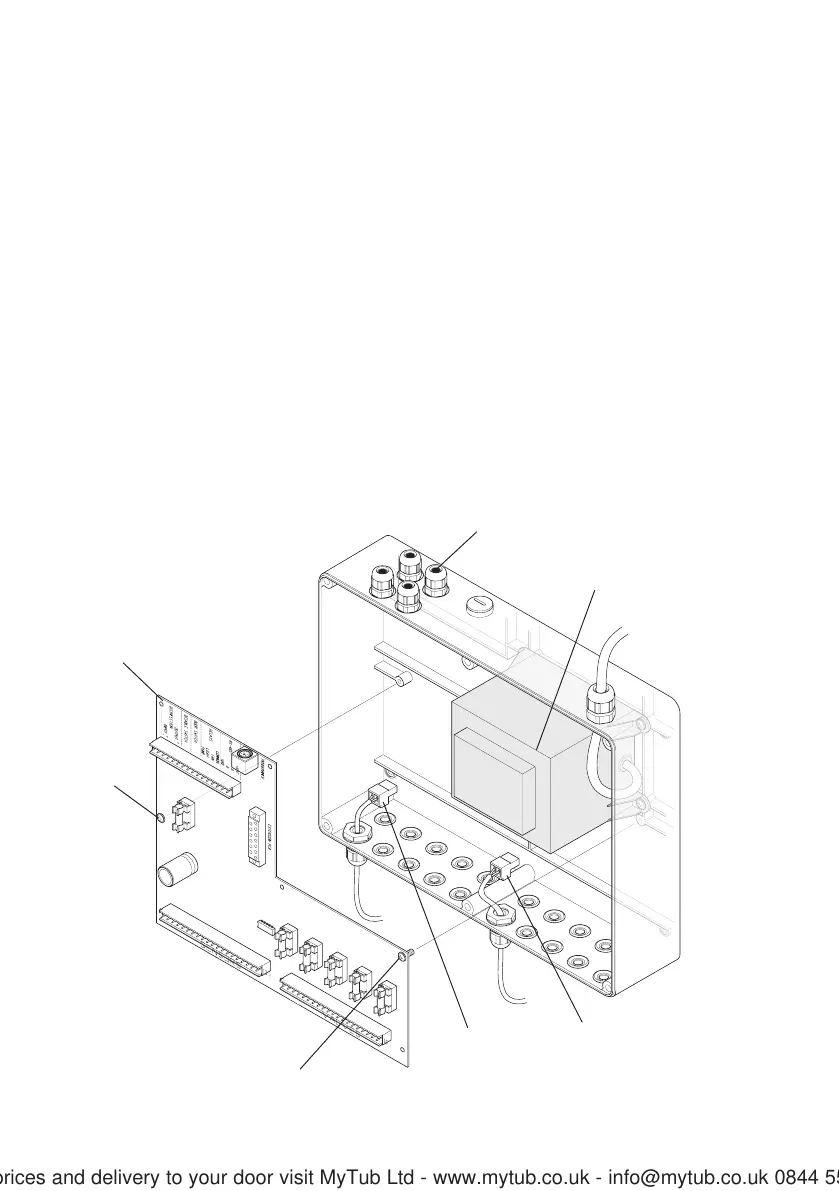
Maintenance Procedure - PCB
1. Isolate the electrical supply to the control box.
2. Remove the cover from the control box.
3. Disconnect the transformer from the PCB.
4. Make a note of the positions of the connections for the sensors and the solenoid
valves.
5. Disconnect the solenoid valves and the sensors connections from the PCB.
6. If necessary, disconnect any auxiliary connections from the PCB.
7. Remove the fixing screws (2 off) that secure the PCB to the control box.
8. Remove the PCB from the control box.
9. Refit the new PCB in reverse order.
10. The control box will now need programming with the hand held programmer (refer
to the Product Manual for the hand held programmer).
Removal and Installation of the PCB
Transformer
PCB
Auxiliary Connections
Sensor
Connections
Solenoid Valve
Connections
Fixing Screw
Fixing Screw
For latest prices and delivery to your door visit MyTub Ltd - www.mytub.co.uk - info@mytub.co.uk 0844 556 1818