8
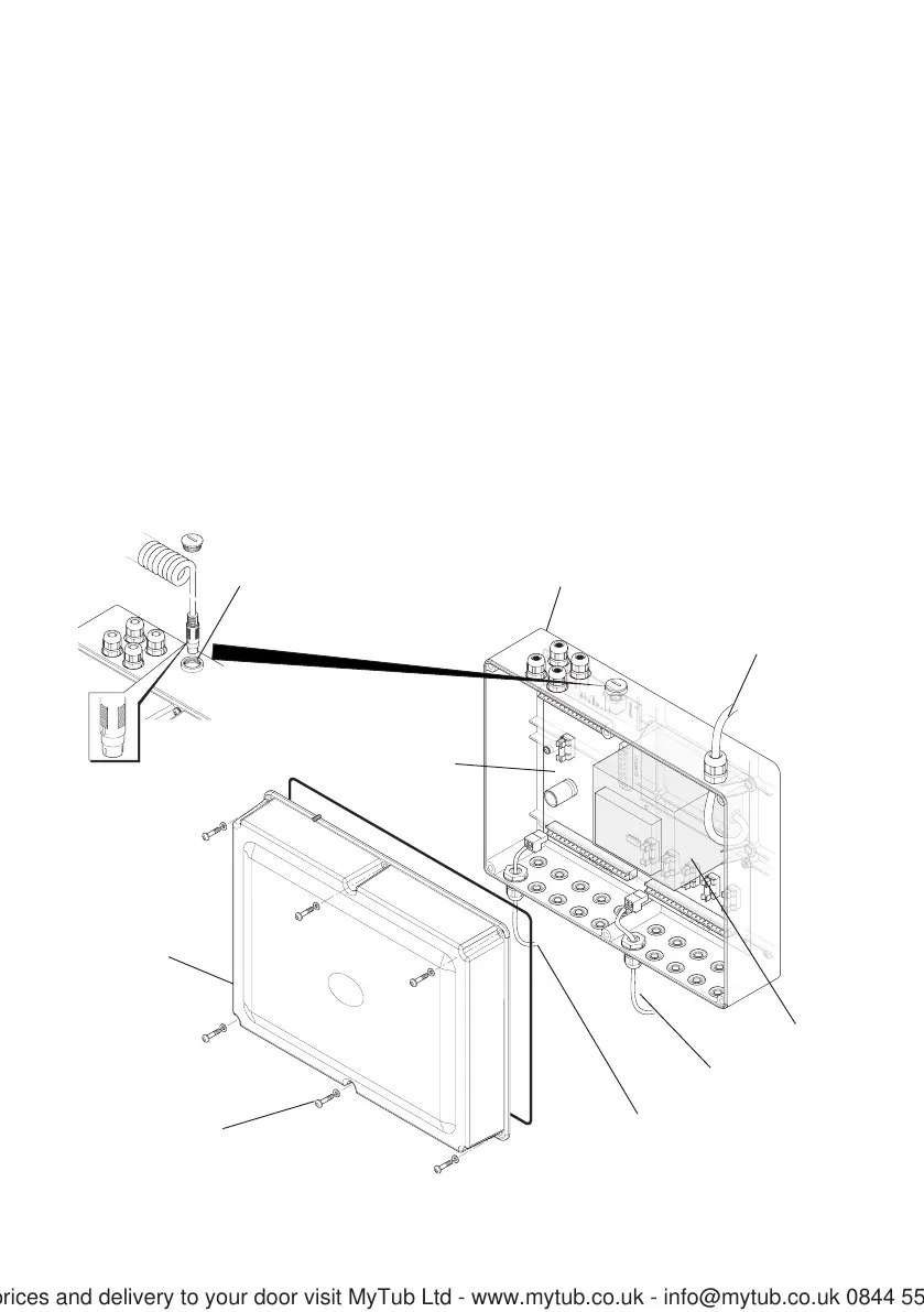
Connections to
Solenoid Valves
Connections to
Pulse Sensors
Transformer
PCB
Cover
Screws
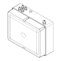
Cover
Installation of the Rada Pulse Control Box
Connections to Auxiliary Units
e.g. Fan, Light , Disinfection
Connection to Mains
Power Supply
Connection Point for
Hand Held Programmer
5. Connect the solenoid valve and sensors to the PCB with the two part connectors.
Make sure that the cables go through the cable glands (supplied with the sensor
and the solenoid valve).
Note! Sensor position identified No. 1 operates solenoid valve No. 1 etc. Inside
the cover of the control box is an information label to be completed by the installer.
The information on this label should identify the position in the building of individual
solenoids and sensors (refer to example on label).
6. Connect the transformer to the mains electrical supply.
7. The control box will now need programming with the hand held programmer (refer
to the Product Manual for the hand held programmer).
8. Fit the cover to the control box and secure with the screws (6 off).
For latest prices and delivery to your door visit MyTub Ltd - www.mytub.co.uk - info@mytub.co.uk 0844 556 1818