Radijator Inženjering d.o.o, 36000 Kraljevo, Živojina Lazića - Solunca br.6, Srbija
tel. +381 36 399 140, fax. +381 36 399 150, http://www.radijator.rs
e-mail: radijator@radijator.rs
42
All lines that are displayed in the intermittent form in the diagram of external connections are
the conductors which should be installed by the technician when connecting the external
devices onto the automation system of the boiler. All the connections of the additional devices
are performed by the technician through three connectors located at the rear of the boiler. Two
connectors are three-pole connectors while one is seven-pole connector. One three-pole
connector serves for the connection of the room thermostat as shown on the label the
connector itself.
For the room thermostats it is important to be battery-powered on, i.e. they
should not have any supply of the voltage of 220 V. On the thermostat for the connection
NC is used (normally closed contact).
The second three-pole connector for connecting the probe for measuring the temperature in
the battery or in boiler for domestic sanitary water. This probe is always supplied with the
boiler. If the probe for measuring water temperature in the battery or in the hot water heater is
not long enough it is possible to extend it with ordinary conductors.
Seven-pole connector is for connecting network cable and for the connection of the
circulation pump and the battery pump i.e. of the heater for sanitary water.
The boiler can operate even if none of the pumps is connected, but manufacturer's
recommendation is that, at least, the pumpa1 (central heating pump) because it has the
function of a security element. It is switched on when the boiler water temperature exceeds 90
degrees Celsius.
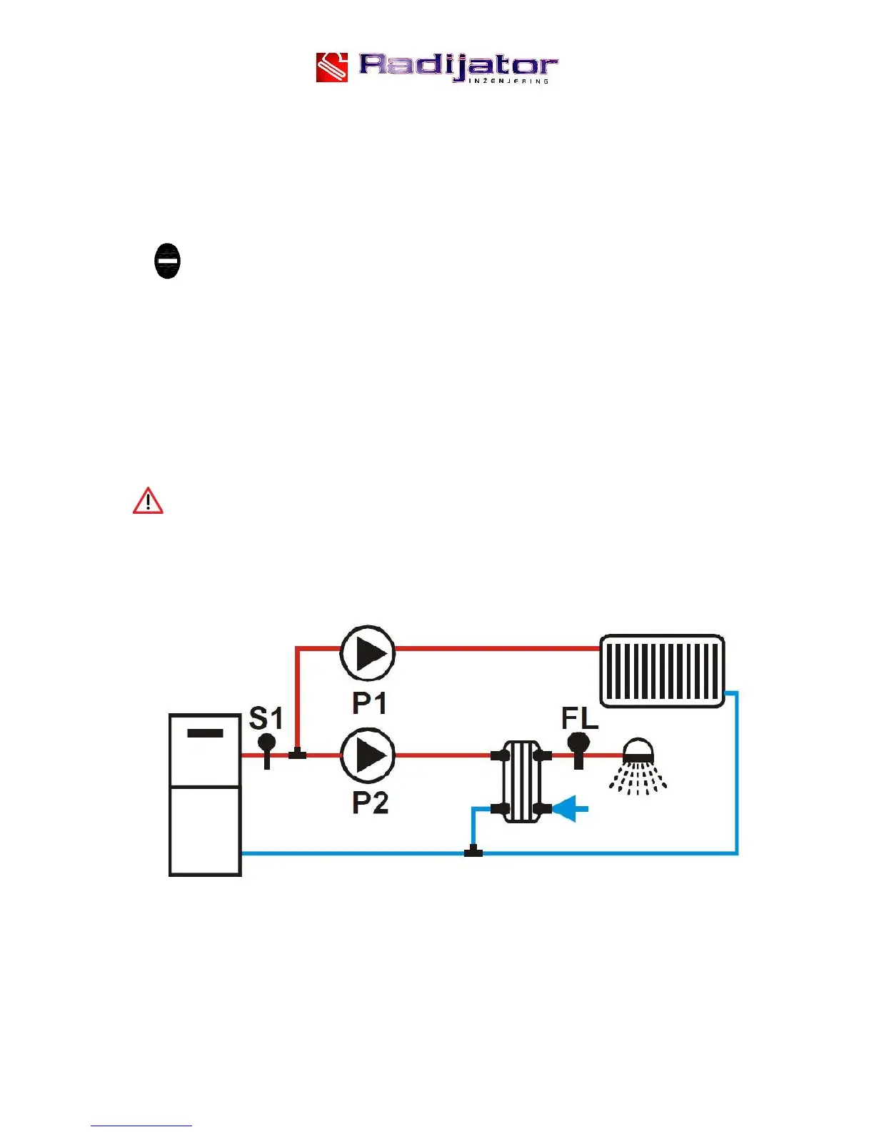
The boiler is adjusted according to the default factory hydro installation as in Figure 8.
Figure 8.
It is obvious that there is only one measuring point S1 and that probe is already positioned.
The second probe that is connected onto the connector on the back of the boiler, in this case,
remains unused.


 To Next Page