Do you have a question about the Radio Shack Realistic DX-150 and is the answer not in the manual?
Details the receiver's circuit components like transistors, diodes, and thermistors.
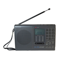
Lists the four main tuning bands and their frequency ranges.
Details the frequencies covered by the band spread system across six bands.
States the intermediate frequency used in the receiver.
Specifies the receiver sensitivity in microvolts (uV).
Mentions the signal-to-noise ratio.
Indicates the image ratio of the receiver.
States the maximum audio output power.
Specifies the type and size of the loud speaker.
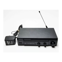
Details power requirements for AC and DC operation.
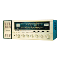
Lists and describes controls located on the front panel of the receiver.
Lists and describes controls located on the back panel of the receiver.
Lists the necessary test equipment for performing alignment procedures.
Outlines the initial conditions and knob settings before starting alignment.
Provides instructions and notes for aligning the Intermediate Frequency amplifier stage.
Details the procedure for aligning the Radio Frequency amplifier stage, including frequency points.
Instructions for aligning the Beat Frequency Oscillator, including notes and setup.
Provides instructions on how to disassemble the receiver's chassis.
Explains the process of assembling or replacing the dial cords.
Specifies the correct setting for B.F.O. Pitch and Antenna Trimmer knobs.
| Type | Communications Receiver |
|---|---|
| Modes | AM, CW, SSB |
| Power Supply | 120 VAC, 60 Hz |
| IF Rejection | >80 dB |
| Frequency Range | 535 kHz to 30 MHz |