DISASSEMBLY/ASSEMBLY
3.1
OVERVIEW AND CASE
The
Model4P
is
modular
in
construction
in
that
it
can
be
disas-
sembled
in
major
component
blocks
after
removal
of
the
case
cover. These major component blocks include the disk drives,
the power supply, main CPU board, the CRT display, and the
monitor
board.
Accessory
components
such
as
the
power
cord,
additional diskettes, and operating manual can be stored
in
convenient recesses
in
the removable
front
cover/base. This
cover/base provides protection for the CRT and disk drives dur-
ing
transport.
It
also serves as the base
in
the non-operating po-
sition
of
the
computer.
The cover/base
is
held in place with snap locks
on
each side.
These
locks
are
positive
action
with
a
protective
boss
to
pre-
vent
accidental
opening
of
the
cover/base.
To
remove,
merely
unsnap the lock and release the catch from the main assembly
latch. The following procedures are noted in sequential order
required
to
provide
access
to
some
of
the
components.
Some
parts
removal
does
not
require
previous
steps.
Those
which
do
are
noted.
For
reassembly
of
unit,
reverse
order
of
disassembly
instructions.
1.
The main
assembiy
of the Model 4P has a removable
cover
which
allows
access
to
all
internal
components
when
removed.
Remove
all
connections
to
the
rear
of
the
unit.
These include the
AC
power cord, printer cable, I/O port
connector, and RS-232-C connector. The printer cable and
I/O port connectors are edge card type connectors
- ex-
ercise
care
in
their
removal.
2.
Place the unit Bezel/CRT face-down
on
a soft surtace to
prevent damage to the CRT.
3.
The
case
is
held
in
place
with
six
screws.
Remove
two
screws
from
either
side
of
the
case
at
the
front
of
the
unit.
To
gain
access
to
the
last
two
screws,
press
down
on
one
end of the carrying handle and then lift the handle from its
recess.
The
final
two
case
mounting
screws
are
accessible
under the handle assembly. These two screws attach the
handle assembly as well
as
the case to the ',nternal rear
mounting plate.
side of the unit. With the rear of the unit toward you, two of
these screws are located at the left just
in
front of the Disk
Drive Assembly and accessibie from the left side of the
chassis
assembly.
The
two
on
the
right
are
accessible
from
the rear of the chassis assembly.
3.
Six other screws are located around the outside edges of
the rear mounting plate. Remove the plate and set
it
aside
for reassembly.
3.3 FRONT BEZEL
1.
The
front
bezel
can
be
removed
from
the
unit
after
the
case
and
rear
mounting
plate
have
been
removed
as
noted
in
Paragraphs
3.1
and 3.2.
2.
Pull the brightness and contrast knobs off the pots from the
front.
3.
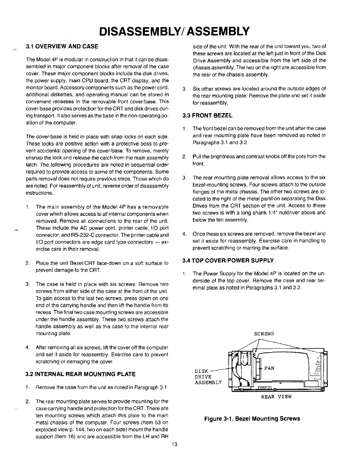
The
rear
mounting
plate
removal
allows
access
to
the
six
bezel·mounting
screws.
Four
screws
attach
to
the
outside
flanges of the metal chassis. The other two screws are lo-
cated to the right of the metal partition separating the Disk
Drives from the CRT section of the unit. Access to these
two screws is with a long shank 1/4" nutdriver above and
below the fan assembly.
4.
Once
these
six
screws
are
removed,
remove
the
bezel
and
set
it
aside
for
reassembly. Exercise
care
in
handling
to
prevent
scratching
or
marring
the
surface.
3.4 TOP COVER/POWER SUPPLY
1.
The Power Supply for the Model 4P is located
on
the un-
derside
of
the
top
cover.
Remove
the
case
and
rear
ter-
minal plate as noted
in
Paragraphs
3.1
and 3.2.
SCREWS
4.
After removing all six screws, lift the cover off the computer
and
set
it
aside
for
reassembly.
Exercise
care
to
prevent
scratching or damaging the cover.
3.2 INTERNAL REAR MOUNTING PLATE
1.
Remove the case from the unit
as
noted
in
Paragraph
3.1
DISK
_-----rTI
DRIVE
ASSEMBLY
FAN
2.
The
rear
mounting
plate
serves
to
provide
mounting
for
the
case carrying handle and protection for the CRT. There are
ten
mounting
screws
which
attach
this
plate
to
the
main
metal chassis of the computer. Four screws (Item
53
on
exploded view
p.
144, two
on
each side) mount the handle
support (Item
16) and are accessible from the
LH
and
RH
13
REAR
VIEW
Figure 3-1. Bezel Mounting Screws
 Loading...


