4.
If
the cable assembly requires replacement, feed the con-
nector through the opening
in
the keyboard base, then in-
stall a tiewrap around the cable just before the insulation
sleeve.
This
serves
as
a
strain
relief
for
the
cable
when
the
keyboard is reassembled. Ensure that this t',ewrap is in the
recess
between
the
opening
in
the
case
and
the
clamping
bosses on the bottom of the case.
5.
Also ensure that
on
reassembly the PCB
is
properly posi-
tioned on the bosses of the base before attaching the top
cover.
•
MOUNTING
SCREWS
o 0
BOTTOM PAN
o
DISK DRIVE
SU
BASSEMBLY
Figure 3·2, Keyboard Cable Strain Relief
3,9
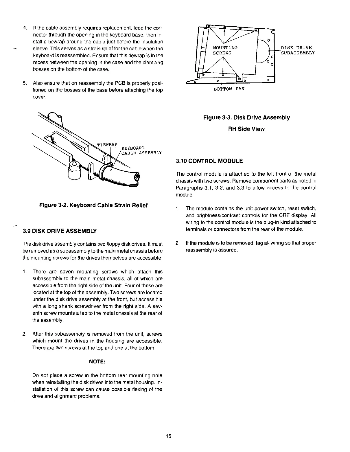
DISK DRIVE ASSEMBLY
The
disk drive assembly contains two floppy disk drives. it must
be
removed as a subassembly to the main metal chassis before
the
mounting
screws
for
the
drives
themselves
are
accessible.
1.
There are seven mounting screws
which
attach
this
subassembly to the main metal chassis, all of which are
accessible from the right side of the unit. Four of these are
located at the top of the assembly.
Two
screws are located
under the disk drive assembly at the front, but accessible
with a long shank screwdriver from the right side. A
sev-
enth screw mounts a tab to the metal chassis at the rear of
the assembly.
2.
After this subassembly is removed from the unit, screws
which
mount the drives
in
the housing are accessible.
There are two screws at the top and one at the bottom.
NOTE:
Do not place a screw in the bottom rear mounting hole
when reinstalling the disk drives into the metai housing. in-
stallation of this screw can cause possible flexing of the
drive and alignment problems.
15
Figure 3·3, Disk Drive Assembly
RH
Side View
3,10 CONTROL MODULE
The control module is attached to the left front of the metal
chassis
with
two
screws.
Remove
component
parts
as
noted
in
Paragraphs 3.1, 3.2, and 3.3 to allow access to the control
module.
1.
The module contains the unit power switch, reset switch,
and brightness/contrast controls for the CRT display. All
wiring to the control module is the plug-in kind attached to
terminals
or
connectors
from
the
rear
of
the
module.
2.
If
the module is to be removed, tag all wiring so that proper
reassembly
is
assured.
 Loading...


