Specifications
Dimension:29*25.1*9.1mm
Weight (With wires): 4. 5g
Channel Quantity: 7 channels
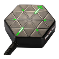
Integrated S ensor: Three-axis g yroscope and three-axis acceleration sensor
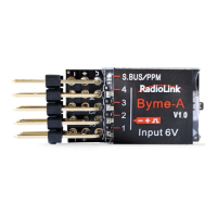
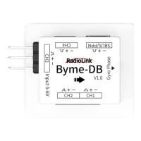
Signal Supported: SBUS/PPM
Input Voltage: 5 -6V
Operating Current: 2 5±2mA
Flight Modes: Stabilize Mode, Gyro Mode and Manual Mode
Flight Modes Switch Ch annel: Channel 5 (CH5)
Motor Lock Channel: C hannel 7 (CH7)
Socket Specifications: CH1, CH2 and CH4 are with 3P SH1.00 sockets; The receiver connect socket is 3 P PH1.25 socket; CH3 is
with a 3P 2.54mm Dupont Head
Transmitters Compatible: All th e transmitters with SBUS/PPM signal output
Models Compatible: All model airplanes with mixed e levator and aileron controls in cluding delta wing, paper plane, J10,
traditional SU27 , the SU27 with rudder ser vo, and F22, etc.
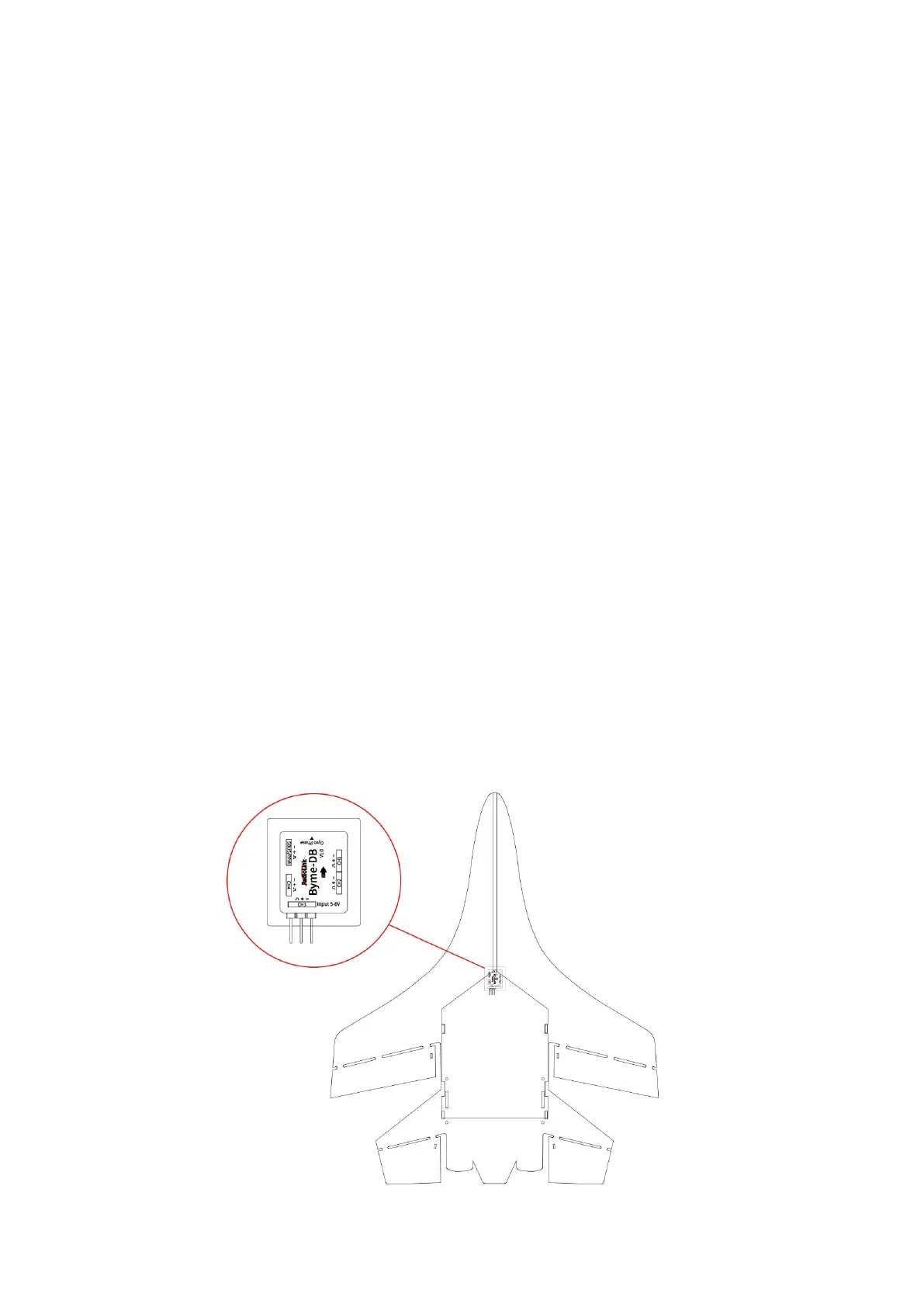
Installation
Make sure the arrow on Byme-DB p oints to the aircraft head. Use 3 M glue to flatly attach Byme-DB to the fuse lage. It is
recommended to install it near the center of gravity of the aircraft. Byme-DB comes with a receiver connect cable which is u sed
to connect the receiver to Byme-DB. When connecting the servo cable and ESC cable to Byme-DB, p lease check whether the
servo cable and ES C cable match th e sockets/head of Byme-DB. If they do not match, the u ser ne eds to modify the ser vo cable
and ESC cable, and then connect the cables to Byme-DB.
 Loading...