D2112/D2112E Installation Manual
Page 5
74-07111-000-D 1/96
© 1995 Radionics
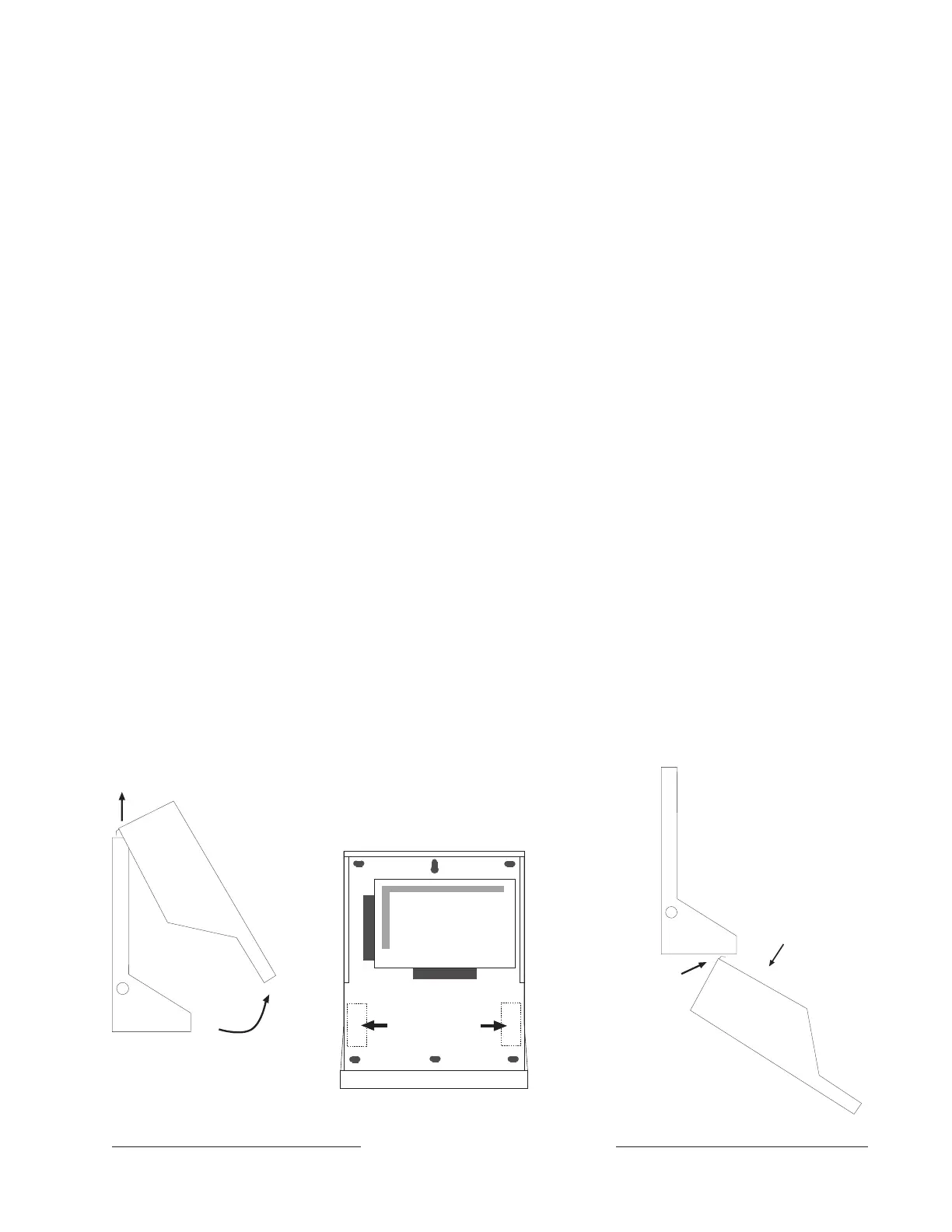
Mount the Enclosure
Lift the bottom of the enclosure cover and remove it
from the base. See Figure 1.
Mount the base in the desired location. Leave a 2"
clearance at the top of enclosure so that you can
easily install the cover.
Run the Premises Wiring
Run the necessary wiring throughout the premises
and pull the wires into the enclosure. Do not make
any connections yet.
Wire Length
The length of the wire run for points is limited only by
the resistance on the loop and potential EMI
(Electro-Magnetic Interference) problems.
On the D2112, wire resistance on the Point 1 sensor
loop must be less than 50Ω. Measure the wire
resistance before installing smoke detectors. Short
the end-of-line resistor before metering the wire.
Resistance on the sensor loops for Points 2 to 8 (1
to 6 on D2112E) must be less than 100Ω with the
end of line resistor shorted and the detection devices
connected.
Maximum wire length for the transformer is 50 feet
(18 AWG, stranded).
Maximum wire length for all keypads combined is
500 feet (22 AWG).
EMI (Electro Magnetic Interference)
AC wiring can induce EMI (both noise and low level
voltage) into adjacent wiring. Run phone and sensor
loop wiring away from AC conductors, including the
transformer wire. Run keypad wiring away from AC
and phone wiring.
EMI may also occur if you install the panel or run
system wires near the following:
• Computer network system
• Fluorescent fixtures
• Telephone cabling
• Ham radio transmitter site
• Heavy machinery and motors
• High voltage electrical equipment
• PBX telephone system
• Public service (police, fire departments, etc.)
using radio communications
• Radio station transmitter site, or other broad-
cast station equipment
• Welding shop
If you think that EMI may be a problem, use shielded
cable. The drain wire for the shielded cable must
have continuity from terminal 3 on the panel to the
end of the wire run.
If continuity is not maintained, the shielded cable
may aggravate potential noise problems rather than
eliminate them. If you cut the drain wire to install
devices be certain to splice it together. Solder and
tape all splices.
Connecting the drain wire to ground at other than
terminal 3 may also produce problems.
Swing cover out from
base at bottom. Lift
cover clear of base.
Base
Cover
Base
Cover
Label showing
Wiring Diagram
Slide cover
tab into slot
on base for
convenient
view of Wiring
Diagram
during
installation.
Mounting locations
for optional
D133 Relay Modules.
Mount base to wall.
Leave at least 2 inches
clearance at top to install
and remover cover.
Figure 1: D2103 Enclosure
 Loading...