Do you have a question about the Radionics D2412 and is the answer not in the manual?
Details FCC Part 15 compliance for digital devices, including interference guidelines.
Covers FCC Part 68 rules for telephone connection, including REN and network impact.
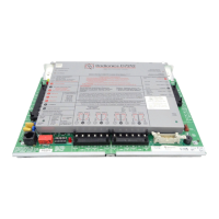
Lists the main components included in the D2412 panel assembly.
Details the hardware components included in the package, like resistors and screws.
Lists literature packs and optional accessories that must be ordered separately.
Details components and documentation included with various keypad models.
Lists Underwriters Laboratories and CSFM approvals for fire warning systems.
Lists UL approvals for various burglary alarm system applications.
Instructions for opening the enclosure and accessing mounting holes.
Covers running wiring, wire length limits, and EMI mitigation.
Instructions for connecting the panel to earth ground for surge protection.
Details connecting the transformer and placing the battery.
Locking standby switch and installing devices without connecting to panel.
Powering down, alarm output terminals, and power calculation.
Connecting keypads and expanders, including wire length limits.
Details the 1.0A auxiliary power output and its voltage range.
Explains programming and connecting external relays via terminals 9 and 10.
Details the powered and supervised Point 1 sensor loop connection.
Details supervised points 2-6 and types of detectors to connect.
Details supervised, non-powered points 2 to 6 and resistor requirements.
Guidance for four-wire smoke detectors, heat detectors, and burglary devices.
UL installation note for wiring sounding devices to external relays.
Details connecting wired/RF point expanders and RF point functionality.
Instructions for wiring the RJ31X jack and phone cord.
Connecting battery and transformer to power up the system.
Instructions on programming the panel using keypad, D5200, or remote programmer.
Moving the standby switch to normal position after programming.
Guide for performing a complete functional test of the panel and devices.
Details the 16.5 VAC, 40VA transformer as the primary power source.
Details the 12V, 7.0Ah battery as secondary power.
Explains battery supervision, trouble indication, and replacement recommendations.
Advises investigating low battery reports and details charging cycles.
Discusses power output protection and extra power needs for devices.
Options for dialing format, communication failure, and ground start systems.
Details Point 1 and Points 2-6 parameters, including voltage ranges.
Explains point scan time and connecting/operating a keyswitch.
Details using Easikey to turn system OFF, its 12VDC option, and UL restrictions.
Instructions for connecting the Easikey door controller using a D133 Relay Module.
UL requirements for burglary alarm sensors, timing, and testing.
UL requirements for fire initiating devices, detectors, and testing.
Specifies sounding device duration and enclosure suitability for UL applications.
Details D8108A enclosure, UL 681, and vibration sensor installation.
Specifies standby battery capacity for burglary applications.
Explains NFPA 72 requirements and formulas for fire system battery calculations.
Details primary/secondary power, auxiliary, and alarm output specs.
Covers operating voltage, environment, arming stations, and compatible accessories.
Details terminals 1-3 for power input and earth ground connection.
Details terminals 4-8 for alarm, auxiliary power, and common connections.
Details terminals 9-20 for external relays and point connections.
Details terminals 21-24 for telephone line connections.
| Brand | Radionics |
|---|---|
| Model | D2412 |
| Category | Control Systems |
| Language | English |