D8128D
Installation
D8128D OctoPOPIT Module Installation Instructions
41343D Page 14 © 2001 Radionics
3.4 Wiring OctoPOPIT Sensor Loops
Only the resistance on the loop limits the number of normally-open and/or normally-closed detection devices
each sensor loop can supervise. Resistance on each sensor loop must be less than 100 ohms with the detection
devices connected.
Certain UL and NFPA applications may limit the number of detection devices. Consult the appropriate UL or
NFPA standards.
The OctoPOPIT detects open, short, closed, normal, and grounded circuit conditions on its sensor loops and
transmits the conditions to the panel. A ground on the positive leg of the sensor loop transmits a shorted
condition for the point. Each sensor loop is assigned a point number and transmits to the panel separately.
Radionics recommends you use twisted-pair wire for the OctoPOPIT sensor loops to avoid EMI problems. Run
wires away from the premises telephone and AC wiring. If you suspect a noisy environment, use shielded cable.
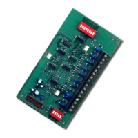
There are two rows of
terminal numbers on the
OctoPOPIT. In the row
closest to the terminal blocks,
the positive outputs for the
sensor loops are labeled P1
to P8. Sensor loop outputs P1
and P2, P3 and P4, P5 and
P6, and P7 and P8 share
common terminals. The
common terminals for each
pair are labeled COM.
Terminate each OctoPOPIT
sensor loop with a 1 kΩ end-
of-line resistor. Attach a
resistor even if you don’t
enable the loop. The
OctoPOPIT comes with a
D105BL resistor for each
sensor loop.
TO PANEL
TO ADDITIONAL OCTOPOPIT
SENSOR LOOPS
OCTOPOPIT
SENSOR LOOPS
1k EOL RESISTOR
RPN D105BL
COM
IN OUT+12V P1 COM P2 P3 COM P4 P5 COM P6 P7 COM P8
D8128D OctoPOPIT
Figure 6: D8128D OctoPOPIT Sensor Loops
Take care not to duplicate point assignments. Points assigned to both an OctoPOPIT sensor loop and a POPIT,
two OctoPOPIT sensor loops, or two POPITs do not function properly.
3.4.1 D8128D OctoPOPIT Switch Settings for D9412 and D9112
ZONEX 1 D8128D Address Switches ZONEX 2
Points 9-127 1 2 3 4 5 Points 129-247
9-16 ON ON ON ON * 129-136
17-24 ON ON ON OFF * 137-144
25-32 ON ON OFF ON * 145-152
33-40 ON ON OFF OFF * 153-160
41-48 ON OFF ON ON * 161-168
49-56 ON OFF ON OFF * 169-176
57-64 ON OFF OFF ON * 177-184
65-72 ON OFF OFF OFF * 185-182
73-80 OFF ON ON ON * 193-200
81-88 OFF ON ON OFF * 201-208
89-96 OFF ON OFF ON * 209-216
97-104 OFF ON OFF OFF * 217-224
105-112 OFF OFF ON ON * 225-232
113-120 OFF OFF ON OFF * 233-240
Refer to the table at right to
set the OctoPOPIT
switches for use with the
D9412 and D9112
Control/Communicators.
Note: For the OctoPOPITs
assigned to points 121-127
and 241-247, be sure to set
Point Input Switch 8 to the
OPEN position.
* Line Termination Switch
(see section
3.1.1.2 Line Termination
Switch Settings).
121-127 OFF OFF OFF ON * 241-247
Table 5: OctoPOPIT Settings - D9412 and D9112