Do you have a question about the Rain Bird IQ-NCC and is the answer not in the manual?
Contact information for Rain Bird IQ-Cloud support.
Contact information for users with a Rain Bird Global Support Plan.
Indicates a hazardous situation that, if not avoided, could result in death or serious injury.
Indicates a hazardous situation that, if not avoided, could result in minor or moderate injury.
Indicates information considered important, but not hazard-related.
Specific safety-related instructions or procedures are described.
Define a series of steps for the user to follow in order to operate the controller.
Notifies the user of important operating instructions related to controller functionality, installation or maintenance.
Indicates that a repetition of previous steps or actions may be required for further operation, or to complete a process.
Welcomes the user and highlights Rain Bird's industry leadership.
Explains the manual's purpose as an addendum to ESP-LX Series Controller guides.
Describes ESP-LX controllers and their upgrade potential with IQ Network Cartridges.
Describes the IQ Central Control System's capability for remote monitoring and programming.
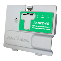
Lists the three types of Network Communication Cartridges available.
Explains Direct Satellites communicate with IQ-Cloud/Computer via Cellular or Ethernet.
Explains Server Satellites communicate with IQ-Cloud/Computer and manage Client Satellites.
Explains Client Satellites communicate with Server Satellites over the IQNet.
Lists the Rain Bird IQ™ products covered in this manual: Ethernet, 4G Cellular, RS-232 cartridges.
Lists the components of the IQ-NCC, including cartridges and cables.
Describes the IQ Port cable or antenna for communication with the IQ-Cloud or IQ Central Computer.
Explains the CM's role in high-speed PE-cable communication between satellites.
Describes the CM Port Straight Cable for connecting IQ-NCC to CM.
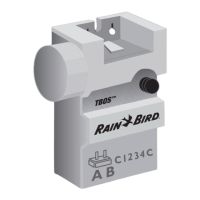
Describes the Y Cable for connecting a radio modem for wireless communication.
Lists configuration options to be determined before installation.
Lists the components included with each IQ-NCC for installation.
Provides steps to unlock and open the ESP-LX Series Controller cabinet.
Details how to locate and remove the knock-out for communication cables.
Explains drilling a hole for an external antenna on the LXMM metal case.
Instructions on removing the cartridge bay cover.
Connects the IQ Port cable or antenna to the cartridge.
Connects the appropriate CM Port cable based on configuration.
Instructions for routing all cables from the cartridge through the front panel channel.
Route the RJ-45 Ethernet cable through the knockout for IQNCCEN cartridges.
Install the required connection module in Slot 0 for the intended configuration.
Connect the keyed mating connector of the CM Port cable to the CM Connection Module.
Route IQNet PE Communication Cable to the CM Connection Module for wired connection.
Secure all installed cables inside the controller and close the front panel.
Connect the PE-Cable metal shield to the orange ground terminal.
Clean the surface to remove any dust or dirt before placing the antenna.
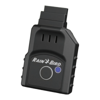
Remove the adhesive backing cover strip from the 4G Cellular antenna.
Place the antenna near the back-plane for clearance when closing the front panel.
Steps to configure an IQ-NCC for a Direct Satellite.
Steps to configure an IQ-NCC for a Server Satellite.
Steps to configure an IQ-NCC for a Client Satellite.
Details on using the NCC Configurator Software for network configuration.
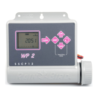
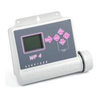
Overview of front panel controls like Reset Button and LED lights.
Explains the meaning of LED lights indicating communication port status.
Details the LED states for IQ Port status across different cartridge types.
Details the LED states for Connection Module Port status.
Details the LED states for Radio Port status.
Displays status for Direct Satellites with IQNCCEN Ethernet cartridges.
Displays status for Direct Satellites with IQ4G Cellular cartridges.
Displays status for Server Satellites with IQNCCEN Ethernet cartridges.
Allows pinging to check communication status with selected clients.
Displays status for Server Satellites with IQ4G Cellular cartridges.
Displays status for Client Satellites with any cartridge installed.
Allows pinging to check communication status with selected clients.
Menu to display communication failures between Server and Client Satellites.
Overview of four types of connection modules for ESP-LX controllers.
The default module for ESP-LXME controllers, used with IQ-NCC when wired comms are not needed.
Optional Flow Smart Module for ESP-LXME controllers, used with IQ-NCC when wired comms are not needed.
Module for LXD/LXIVM satellites requiring wired communications with other satellites.
Module for LXME satellites requiring wired communications with other satellites.
Steps to remove an existing base module from the controller.
Orient and firmly fasten the connection module onto the satellite backplane.
Connect the green and yellow ground wire to the grounding post on the satellite backplane.
Details on attaching PE-Cable shield and routing grounding wire for CM modules.
Steps to install a SIM card in the IQ4G cellular cartridge.
FCC compliance information for Class B digital devices.
| Brand | Rain Bird |
|---|---|
| Model | IQ-NCC |
| Category | Control Unit |
| Language | English |