1
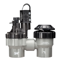
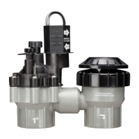
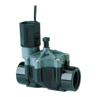
ANTI-SIPHON VALVE
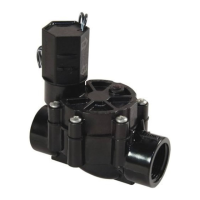
OPERATION MANUAL: DAS-075 / ASVF 3/4” DAS-100 / ASVF 1”
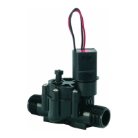
For use with all standard sprinkler controllers with 24 volt AC out-
put. The DAS / ASVF valves are diaphragm anti-siphon valves
with flow control and atmospheric vacuum breaker.
NOTE: These Rain Bird valves are designed for use with static water
pressures of a MAXIMUM of 150 PSI. For higher pressures, a pressure
regulator should be installed. These valves are for outdoor watering use
only.
For dirty water systems-using wells, lakes, ditches, etc. for your
water supply, be sure to install a 100 mesh (or finer) wire filter or
screen filter before the electric valves. For use in cold water, less
than 110°F (43.3°C), applications only.
ANTI-SIPHON VALVES FOR BACKFLOW PREVENTION
The DAS/ASVF models meet or exceed most building code requirements for
connecting a sprinkler system to a city water supply.
These valves prevent the possibility of back siphoning of water from sprinkler
lines into the drinking water.
The anti-siphon valves must be installed at least 6 inches above the highest
sprinkler or elevated piping in the circuit to meet most codes, (See Diagram 1).
(Consult local building code.)
CAUTION: Do not use this anti-siphon valve as a main line backflow device,
nor as a master valve. It is not designed nor approved to be under constant wa-
ter pressure on both sides of valve. This valve must not be operated continu-
ously for more than twelve (12) hours. Do not install any other valves down
stream. If installed incorrectly with constant pressure on both sides of valve, it is
possible that the valve will fail or burst.
HOW TO SELECT THE RIGHT VALVE SIZE
The valve size (3/4" or 1 ") is determined by the water flow (measured in gallons per minute, or GPM) of the main line
or the sprinkler circuit.
3/4" VALVES: 13 GPM or less.
1" VALVES: 14 GPM or more.
1 " valves and pipes allow longer runs and more sprinkler heads per circuit, as well as potentially reducing the total
number of valves required.
ASSEMBLY OF SPRINKLER VALVES TO PIPE
A sprinkler system is made up of one or more groups of sprinklers (called circuits) each operated by its own control
valve. Study the illustrations and follow the instructions for proper assembly.
6”
6”
Inlet
Outlet to Sprinklers
Wires to Controller
Test this connection
for water tightness
before attaching
outlet pipe.
#1
The valve
must be
mounted at
least six
inches above
the highest
sprinkler on
the circuit.