
M
Megan DominguezJul 27, 2025
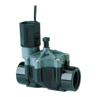
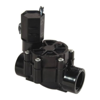
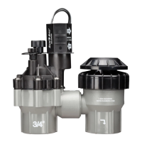
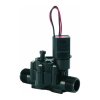
Why does my Rain Bird 100-DV Control Unit valve slam on and off?
- AAngela BartonJul 27, 2025
If your Rain Bird Control Unit's valve is slamming on or off, causing water hammer, the issue might be high water pressure. Check your system's water pressure. If it exceeds 80 psi (5,5 Bars), you should install a pressure regulator on the line before the valve. This will reduce the water pressure and prevent the valve from slamming.