181
INTRODUCTION
18
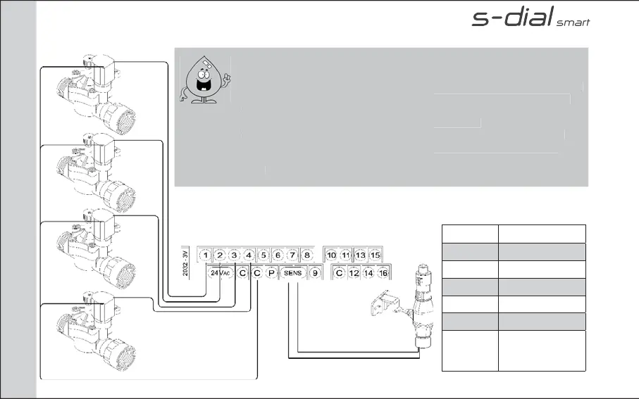
ELECTRICAL CONNECTIONS
sigla descrizione
2032 - 3v Battery
1 - 16 Sector output
24 vac 24 vac inlet
SENS Rain sensor input
C Common
P Pump control
or master valve
Output
Each 24 VAC electric valve is equipped with two black cables. The fi rst one
identifi es the number of the area and is to be connected to of the outputs
numbered in the terminal compartment. The second one is the common cable
that will be connected to the Exit C in the terminal compartment along with
other common cables of all electric valves.
The cables of the 24Vac electric valves have no polarity.
Connect the rain sensor wires cables to the output marked SENSOR in the
terminal compartment.
If using the INDOOR model, connect the transformer’s cables to a 24-vac
input.
Each 24 VAC electric valve is
ed with
identifi es the number of the area and is to b
numbered in the terminal compartment. Th
that will be connected to the Exit C in the te
h
r
mm
n
l
f
ll
l
ri
v
lv
The cables of the 24Vac electric valves have
Connect t
e rain sensor wires ca
es to t
e
terminal compartment.
If using the INDOOR model, connect the tra
ut