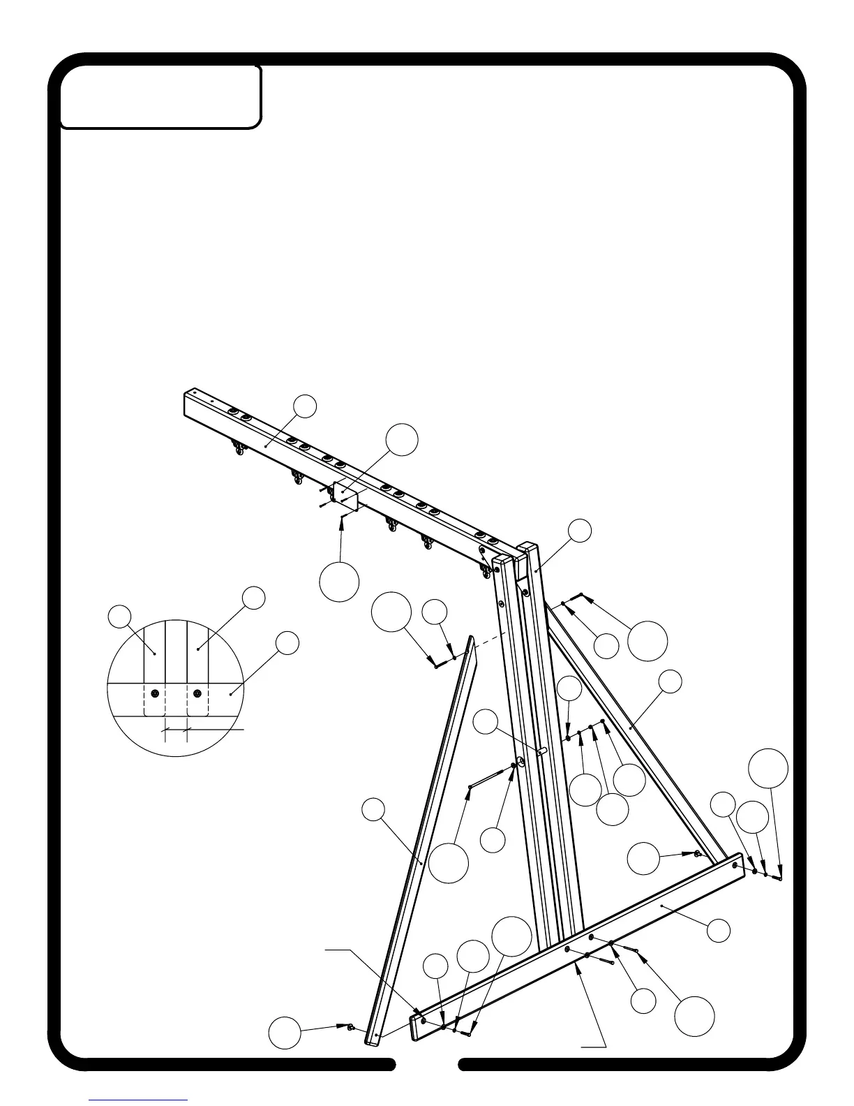
81
N23
H158
H1
H108
26
26
H1
H108
H30
H126
H11
H3
H139
H3
N4
H3
H11
H17
H28
H30
H126
H11
H3
48
H116
H3
79
COUNTER-SUNK
HOLES SHOULD
BE UP
BOTTOMS
FLUSH
D
3 1/4" - 3 3/8"
INSET A
79
79
48
*NOTE: Pre-drill all holes for Lag Bolts with the appropriate drill bit.
1. Attach Ground Runner
(48)
to Swing Beam Support Legs
(79)
using 3/8" Hardware
(H3) (H116)
.
The bottom of the Ground Runner
(48)
should be flush with the bottoms of the Swing Beam
Support Legs
(79)
and the spacing between the Support Legs should be between
3 1/4" and 3 3/8"
(as shown in Inset A).
*NOTE: Ground Runner (48) must be square with the Swing Beam Support Legs (79).
2. Attach Swing Beam Support Legs
(79)
together with 3 1/4" PC Pipe
(N4)
using 3/8" Hardware
(H3)
(H11) (H17) (H28) (H139).
Tighten hardware until there is
3 1/8"
between Swing Beam Support
Legs
(79)
.
*NOTE: Support Wings (26) must be oriented in opposite directions before inserting 3/8"
Hardware (H30).
3. On a flat surface, insert 3/8" Hardware
(H30)
into pre-drilled holes in Support Wings
(26)
using a
hammer. Attach Support Wings
(26)
to Ground Runner
(48)
using 3/8" Hardware
(H3) (H11) (H126)
.
4. Attach Support Wings
(26)
to Swing Beam Support Legs
(79)
using 1/4" Hardware
(H1)
and 5/16"
Hardware
(H108)
.
5. Center Plaque
(N23)
on the Swing Beam
(81)
and attach using #10 Hardware
(H158)
.
34
Step 16
Swing Beam Assembly