Preparing for use
R&S
®
NRP Series
14Getting Started 1419.0170.02 ─ 16
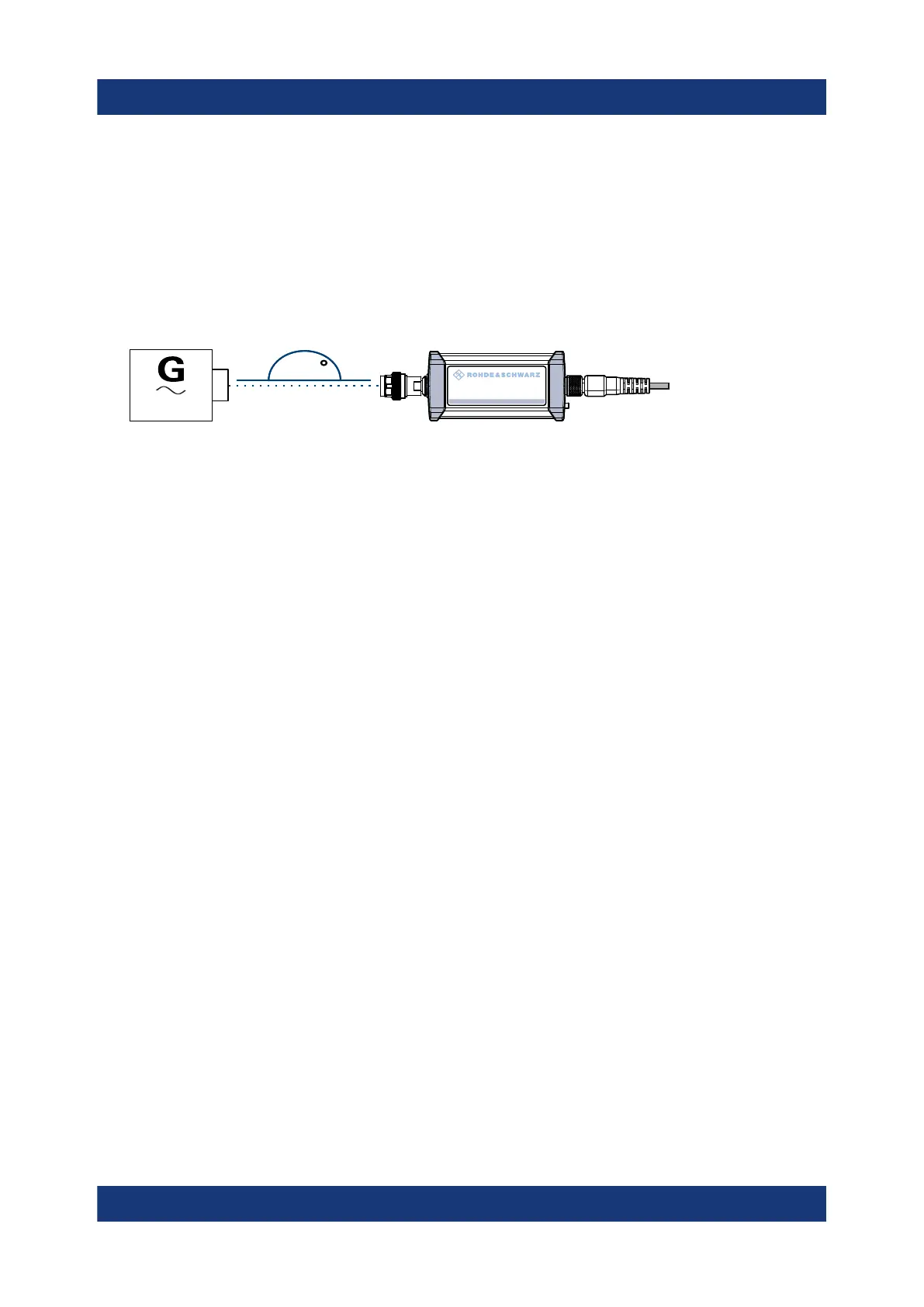
2. Inspect both RF connectors carefully. Look for metal particles, contaminants
and defects.
If either RF connector is damaged, do not proceed, because the risk of dam-
aging the mating connector is too high.
3. Insert the RF connector straight into the RF output of your DUT. Take care not
to tilt it.
180
NRP
3-Path Diode Power Sensor
MHz to GHz, 100 pW to 200 mW (−70 dBm to +23 dBm)
SMART SENSOR TECHNOLOGY
4. NOTICE! Risk of damaging the center pin of the RF connector. Only rotate the
hex nut of the RF connector. Never rotate the power sensor itself.
Tighten the RF connector manually.
5. Tighten the RF connector using a torque wrench with the nominal torque rec-
ommended in Chapter 4.1, "RF connector", on page 28 to ensure maximum
measurement accuracy.
To disconnect from the DUT
1. NOTICE! Risk of damaging the center pin of the RF connector. Only rotate the
hex nut of the RF connector. Never rotate the power sensor itself.
Carefully loosen the union nut at the front of the RF connector of the power
sensor.
2. Remove the power sensor.
3.5 Powering the power sensor
The electrical power for the R&S NRP series power sensor is supplied over one
of the following interfaces:
●
Host interface
See Chapter 4.3, "Host interface", on page 30.
●
LAN PoE interface
Available only for LAN power sensors. See Chapter 4.5, "LAN PoE interface",
on page 31.
Powering the power sensor
 Loading...


