Preparing for use
R&S
®
NRP Series
22Getting Started 1419.0170.02 ─ 16
2. NOTICE! Risk of sensor damage. Only use PoE power sourcing equipment
(PSE) as described in "Choose the PoE power sourcing equipment (PSE) with
care" on page 15.
Connect the RJ-45 Ethernet connector of the sensor to the output of the PoE
injector.
3. Connect the PoE injector to a power supply.
4. Connect the input of the PoE injector to the non-PoE Ethernet switch.
5. Connect the controlling host to the non-PoE Ethernet switch.
6. Establish a connection between the power sensor and the network.
See Chapter 3.7.3.2, "Establishing a connection to the network", on page 23.
Setup with a PoE injector
HOST
INTERFACE
IN: 3 V or 5 V logic
OUT: min. 2 V into 50 Ω
max. 5.3 V
TRIG2
I/0
PoE
SMART SENSOR TECHNOLOGY
NRP
2 3 4
5
6
7
8
1
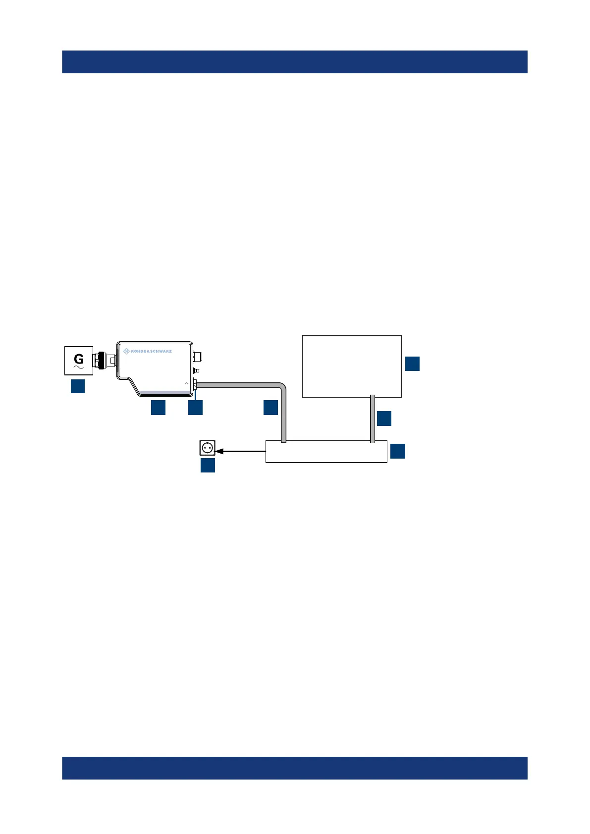
Figure 3-5: Setup with a PoE injector
1 = Signal source
2 = LAN power sensor
3 = RJ-45 Ethernet connector
4, 6 = RJ-45 Ethernet cable
5 = Controlling host
7 = PoE injector
8 = AC supply
1. NOTICE! Incorrectly connecting or disconnecting the power sensor can dam-
age the power sensor or lead to erroneous results. Ensure that you connect or
disconnect the power sensor as described in Chapter 3.4, "Connecting to a
DUT", on page 13.
Connect the power sensor to the signal source.
Connecting to a controlling host
 Loading...


