Instrument Tour
R&S
®
RTC1000
18Getting Started 1335.7346.02 ─ 02
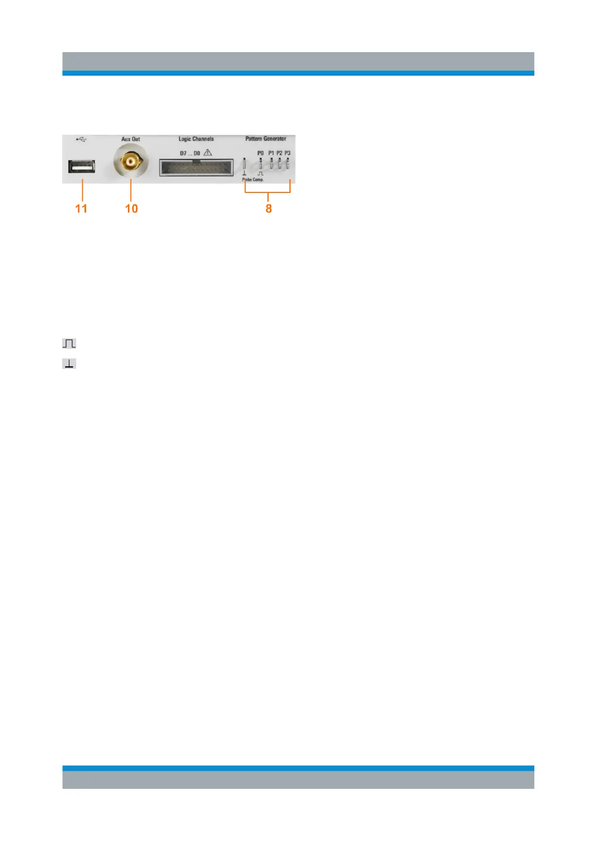
4.1.2 Other Connectors on the Front Panel
PATTERN GENERATOR (8)
Connectors for the pattern generator P0, P1, P2, P3.
PROBE COMP. (8)
Probe compensation terminal to support adjustment of passive probes to the
oscilloscope channel.
Square wave signal for probe compensation.
Ground connector for probes.
AUX OUT (10)
Multi-purpose BNC output that can function as pass/fail and trigger output, output
for component testing, and as function generator output (with option R&S RTC-
B6).
USB type A (11)
USB 2.0 type A interface to connect a USB flash drive for storing and reloading
instrument settings and measurement data, and to update the firmware.
4.2 Rear Panel
Figure 4-2 shows the rear panel of the R&S RTC1000 with its connectors.
On the back panel of the instrument, you find Ethernet and USB interfaces.
Optional interfaces are not available.
Rear Panel

 Loading...


