Instrument Tour
R&S
®
RTM2000
24Getting Started 1317.4710.02 ─ 05
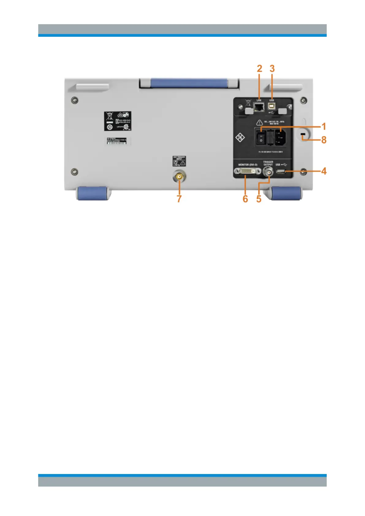
Fig. 3-2: Rear panel view of R&S
RTM
1 = AC power supply connector and main power switch
2 = LAN connector
3 = USB connector, type B
4 = USB connector, type A
5 = Trigger output
6 = DVI-D connector for external monitor
7 = External trigger input
8 = Kensington lock slot to secure the instrument against theft
AC Supply: mains connector and main power switch
The instrument supports a wide range power supply. It automatically adjusts to the cor-
rect range for the applied voltage. There is no line voltage selector.
The AC main power switch disconnects the instrument from the AC power line.
LAN
8-pin connector RJ-45 used to connect the instrument to a Local Area Network (LAN).
It supports up to 100 Mbit/s.
USB TYPE B
USB (universal serial bus) interface of type B (device USB) to be used for remote con-
trol of the instrument.
Note: Electromagnetic interference (EMI) can affect the measurement results. To
avoid any impact, use only USB connecting cables with a maximum length of 1 m.
USB TYPE A
USB interface of type A (host USB) to connect a printer, or a USB flash device for file
transfer. Another connector of this type is located at the front panel.
MONITOR (DVI-D)
Digital connector for an external monitor.
Rear Panel