10
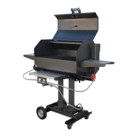
2 ea. 5/16” x 2”
Bolts
6 ea. 5/16”
Washers
2 ea. 5/16” x
3/4” Bolts
4 ea. 5/16” Nuts
Step 2
1) Place the Rear Axle onto the Pedestal Riser/Burner Assembly and attach using
5/16” x 3/4” Bolts (2 ea.), 5/16” Washers (2 ea.) and 5/16” nuts 2 ea.). Tighten
these screw and nuts temporarily.
2) Attach front castor assembly to the skid weldment using 5/16” x 2” Bolts
(2 ea.), 5/16” flat washers (4 ea.) and 5/16” nuts (2 ea.), There should be one flat
washer on top of the flange on the skid and one flat washer under the front axle
assembly. Note: The Front Axle will need to set completely on the horizontal
flange. Do not allow either edge of the axle to fall of this surface. Be sure the
tighten these bolt to prevent the axle from moving.
3) Check to make sure the burner/riser set level. If it is not, loosen the nuts on the
rear axle and adjust until the units sets as level as possible. Tighten these nuts
securely to lock the leveling into place.
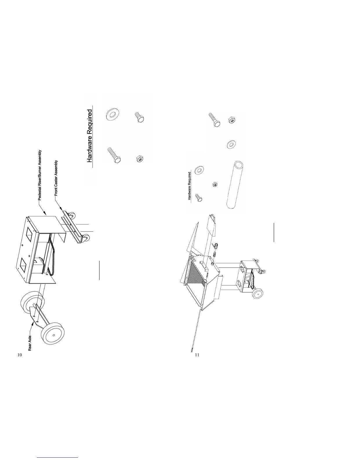
11
Handle Cover
1 ea. Loose
1 ea. Installed onto
Step 3
1) Place the boiler tub onto the skid assembly as shown, it is best if the shelf mounts are on the same side as the
front/castor axle. Secure using 5/16” x 2” screws (4 ea.), 5/16” washers (8 ea.) and 5/16” nuts. Tighten firmly to
lock into place. Note: the washers should be where there is one on top of the tub flange and one in under the
burner/riser.
2) Be sure there is Teflon tape on both ends of the 1 1/2” nipple. Screw the 1 1/2” nipple into the collar on the lower
side of the boiler. Next screw the 1 1/2” Ball Valve onto the nipple. Tighten the ball valve assembly to insure that
it does not leak.
3) Install the side shelf onto the side of the Boiler Tub using the 3/8” x 1” Bolts (2 ea.), 3/8” Washers (4 ea.) and 3/8”
Nuts (2 ea.) Snug these to secure the shelf into place.
4) Slide the Handle Rod through the hole provided in the front of the Basket. Lock this into place by sliding th Handle
Cover on the blank end of the Rod.
5) Attach the Hose/Regulator onto the remaining fitting on the Burner Tube and tighten into place. Again be sure to
tighten the nut so as to prevent any gas from leaking.
6) Finish the Boiler Assembly by completing the step on Page 15.
4 ea. 5/16” x 2”
3/4” Bolts
8 ea. 5/16”
Washers
2 ea. 3/8” x
1” Bolts
4 ea. 5/16”
Nuts
2 ea.
3/8” Nuts
4 ea. 3/8”
Washers
 Loading...