12
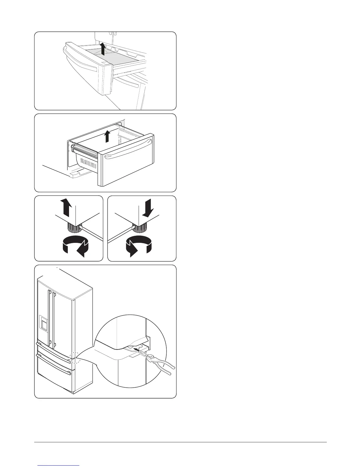
Removing the Upper Freezer Drawer Inner
Compartment
Open the drawer as far as possible. Remove the ice tray. Pull
the rear section of the drawer inner compartment upwards
slightly to enable the front section to be released from the
door (Fig.4.5).
Hold and pull the front section of the inner compartment
upwards to remove it from the refrigerator.
Removing the Lower Freezer Drawer Inner
Compartment
Open the drawer as far as possible. Pull the rear section of the
drawer inner compartment upwards slightly to enable the
front section to be released from the door (Fig.4.6).
Hold the front section of the inner compartment and pull it
upwards to remove it from the refrigerator.
Adjustable Feet
Make sure that the appliance is on solid level ooring. If the
refrigerator is placed on a plinth, at, strong and re resistant
materials must be used.
This appliance has front adjustable feet, which can be used to
level the appliance.
Insert a suitable at screwdriver into the slots of the
adjustable feet. Turn the screwdriver clockwise to raise the
feet (Fig.4.7), and anti-clockwise to lower the feet (Fig.4.8).
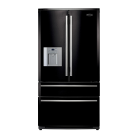
Levelling the Doors
If the door heights are uneven, spacer rings (supplied) can be
inserted to raise the door level.
Raise the door up from the lower hinge. Using a suitable pair
of pliers, insert a clip ring between the door and hinge
(Fig.4.9). Up to three clip rings can be inserted as required.
Installing the Bottom Decorative Strip
and Handles
The supplied decoratiove strip should be xed to the base of
the refrigerator, using the 2 screws provided.
The door handles x onto mounting studs (supplied).
1. Screw the mounting studs into the holes located on the
door shells.
2. Place the handle rmly over the mounting studs.
3. Using the M3 Allen key, tighten the grub screw xing
the handle to the door.
Do not over-tighten the grub screw.