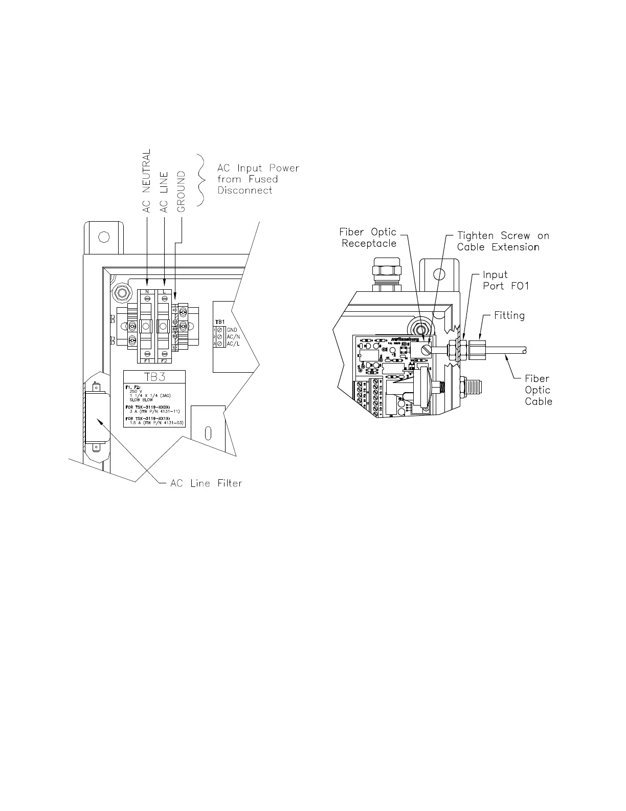
FIBER OPTIC CABLE
(See Figure 5)
Remove the tting from the ber optic input port
(FO1 - FO6) on the side of the control panel and
slide over one end of the ber optic cable. Open
the control panel door. Insert the end of the ber
optic cable through the input port tting and into
the hole of the black rectangular ber optic recep-
tacle on the ber optic receiver module. Tighten
the screw of the ber optic receptacle onto the at
of the cable extension and secure the tting on
the side panel. Route the ber optic cable to the
rotator and connect the other end of the cable to
the ber optic input tting of the rotator.
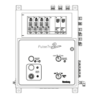
Figure 4: AC Input Power Connections
The ber optic cables are integrated into ¼” tubing
for mechanical protection. A minimum bend radius
of 3" is required. Care must be taken to prevent
kinking for protection of the ber optic cables.
Avoid exposure of the cable ends to chemicals
such as paint or solvents. Exposing the cable
ends to such chemicals will cause damage and
can severely reduce the ability of the cable to
transmit light.
The control panel is precongured for 115 VAC or
230 V AC depending on the model number. Refer
to the "Parts Identication" section of this manual
and the product specication label located on the
control panel.
PNEUMATIC
CONNECTIONS
(See Table 2)
All pneumatic connections are made to the right
side of the PulseTrack 2 control panel. System
components should be installed to minimize the
length of pneumatic control lines. This will max-
imize the rotator speed control response. Tubing
may exceed the maximum lengths as indicated in
the "Specications" in the "Introduction" section of
this manual dependent on the specic installation
requirements; however, this could degrade overall
speed control performance.
Figure 5: Fiber Optic Cable Installation