Click the SmartView icon to begin linking the Head-End Controller. For initial setup, the SmartView Head-End will need
to be connected to the internet. Provide a 120v backed up power source or RATH
®
RP7700104S. Reference manual
RP8500510 for SmartRescue phone wiring and manual RP8500PBXG for Command Center phone wiring.
Visual Setup:
1. Install the SmartView Controllers before setting up the Head-End (see instructions on page 3).
2. Power on the Head-End and wait for the software to load.
3. Click the SmartView icon to begin linking the Head-End Controllers.
4. On the Conguration Screen, enter each SmartView ID installed at your location.
5. Click Submit.
Note: If you see an error, re-check that a proper ID was entered.
6. The IDs will be displayed on the next page.
7. Once successfully linked, you will see a list of the devices with a view icon next to each.
Note: Wait at least 2 minutes to allow the SmartView devices to link before testing.
Note: To verify operation, click the view icon for one of the devices.
In-Building Intercom Master Setup
Page 8
LAN Setup
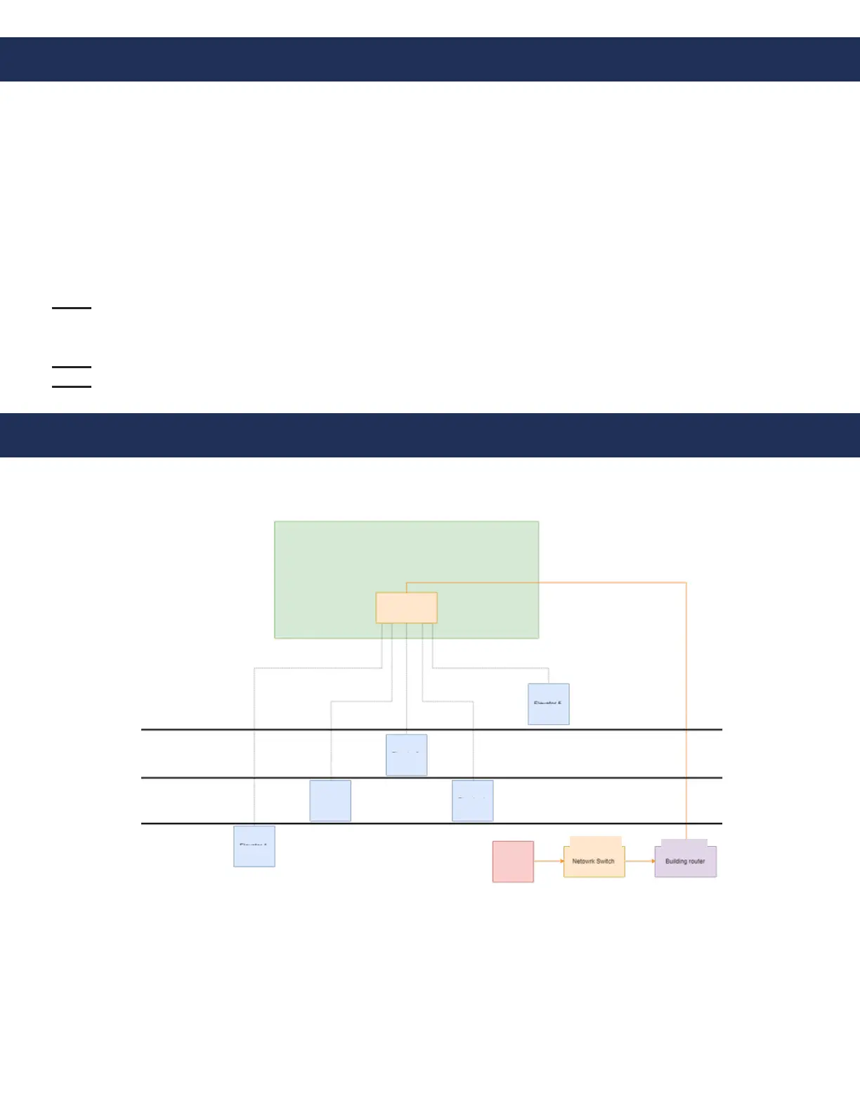
To ensure operation if the external internet is compromised, verify the Head-End and Controllers wire back to the
same network switch or series of network switches. See wiring example below.
Machine Room
Network Switch
Elevator 6
Elevator 3
Elevator 4
Elevator 2
Elevator 1
Head End
Network Switch
Building
Router
Floor 1
Floor 2
Floor 3
Floor 4